

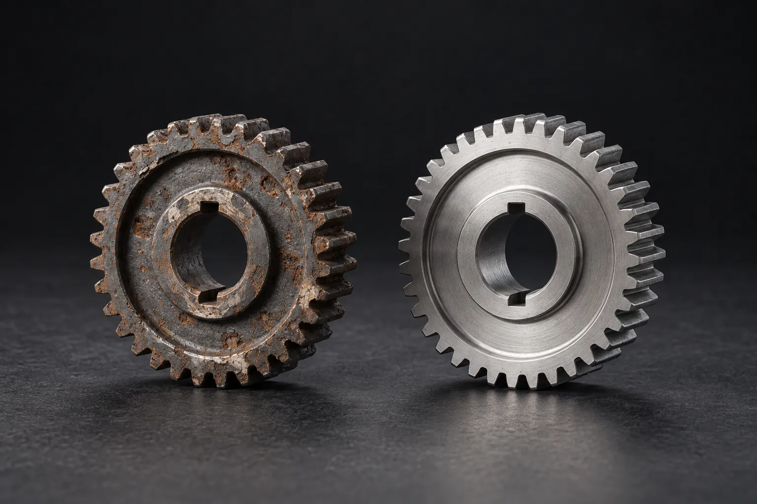
What reverse engineering actually is
Reverse engineering is the process of recovering the full, manufacturable design of a part from the part itself, rather than from a drawing or a CAD file. You start with a physical component, often the only one left, and you work backwards. You measure its geometry, you establish what it is made from and how it was finished, you understand the function it performed and the loads it carried, and you rebuild a complete design definition that another engineer could manufacture from cold.
The distinction worth holding onto is that reverse engineering is not copying. Copying captures a shape. Reverse engineering captures intent. A copied part reproduces whatever was on the sample, including its wear, its damage and the original design mistakes that may have caused it to fail. A reverse-engineered part reconstructs what the designer meant the part to be when it left the drawing board, which means it can be made correct again, and better than the original.
The output of the work is therefore not a sketch and not an approximation. It is a parametric CAD model that carries the part's datums, fits and feature relationships, and a clean manufacturing drawing produced from that model. From those two things the part can be made, inspected against its own definition, and reordered years later without the original sample ever being needed again. The first time a part is reverse engineered is the last time it depends on a single fragile physical original.
When reverse engineering is the right route
Reverse engineering is needed whenever the normal route to a replacement part has closed. In practice that happens in a small number of recognisable situations, and most engineers reading this will recognise at least one of them.
- The part is obsolete. The original manufacturer no longer makes it, or no longer exists. The machine is sound, but one component has no source.
- The line is discontinued. The supplier still trades but has dropped the product, or the minimum order quantity to restart production is far larger than the handful of parts you actually need.
- The drawings are gone. They never existed, were never digitised, or left the building with the engineer who held them. The part exists, but its definition does not.
- The part has failed or worn in service. The asset is down or close to it, and there is no time to search a global supply chain for a component that may not be found.
- You want a second source. You are tied to a single supplier on a critical part, and you want an independent, documented UK source so a price rise or a supplier failure cannot stop your line.
A worn or incomplete component can still provide valuable evidence. Feasibility depends on how much information can be recovered and whether uncertain features can be resolved from mating parts, records or further investigation.
There is one situation where reverse engineering is not the answer, and it is worth being honest about. If you hold a complete, accurate, current drawing of the part, you do not need reverse engineering at all. You need manufacture to a drawing, which is a different and simpler job. Reverse engineering earns its place precisely when that drawing does not exist.
The full method, stage by stage
The method below is the complete route from a worn part on the bench to a finished, inspected replacement. Not every job uses every stage in the same depth. A simple turned bush moves quickly. A cracked casting that keeps failing in the field demands real time on stages 6 and 7. The skill is knowing where the engineering judgement matters most for the part in front of you.
Stage 1: Understanding the part and its duty
Before anything is measured, the part has to be understood as a working component. Where does it sit in the machine. What does it bear against, seal against or transmit load to. What were the temperatures, pressures, speeds and media it lived with. Was it failing, or simply obsolete. A bush that wore out under a side load is a different problem from an identical-looking bush that cracked from thermal cycling, and the two will be reverse engineered differently even though they measure the same.
This stage is mostly conversation and inspection, and it sets the priorities for everything after it. It is where the critical features are identified, the ones that must be held precisely because the part's function depends on them, and separated from the cosmetic features that only have to be close.
Stage 2: Measurement and metrology
For parts with regular, machinable geometry, measurement is done by metrology: hand measurement with micrometers, vernier and bore gauges, height gauges, thread gauges, radius gauges, and where the accuracy demands it a coordinate measuring machine that probes the part and reports feature positions against datums. Diameters, lengths, bores, threads, keyways, hole patterns and surface finishes are all recorded.
Critical features need suitable measurement methods and cross-checks. A measured size is not automatically the intended design size: wear, coatings, temperature and measurement uncertainty can all affect it. For example, a shaft measured at 24.98 mm cannot safely be assumed to have been designed at 25 mm. The mating bearing, required fit, surviving surfaces and any records must be considered before a nominal dimension and tolerance are agreed.
Stage 3: 3D scanning and digitising form
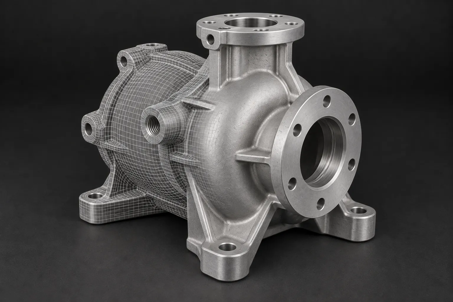
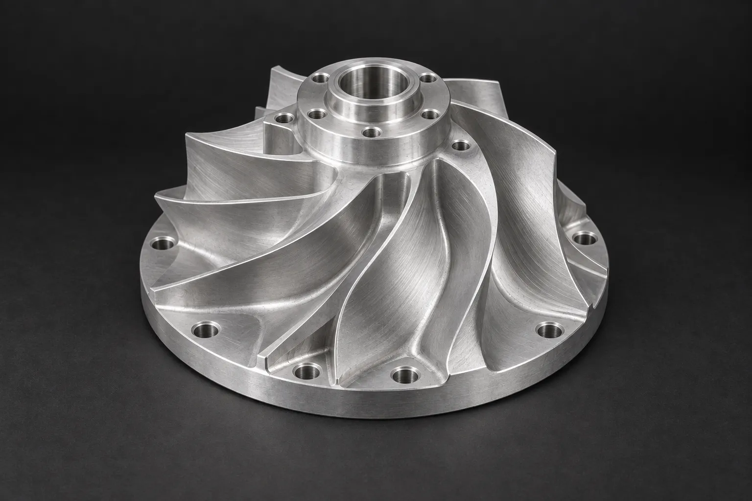
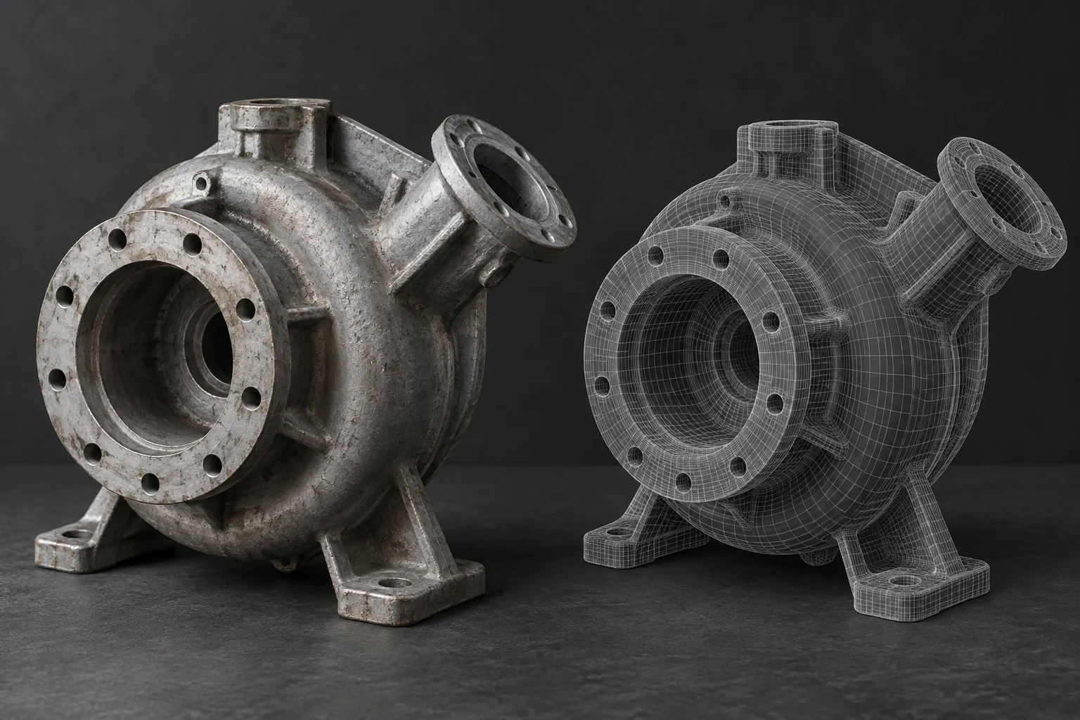
Where the geometry is complex, organic, cast or freeform, hand metrology cannot capture it efficiently and 3D scanning is used instead. Structured-light and laser scanners capture the surface of the part as a dense point cloud, typically millions of points, which is processed into a mesh. Scanning is the right tool for impeller blades, manifold castings, turbine housings, ergonomic handles, worn profiles and any surface that is defined by its shape rather than by a handful of dimensions.
Scanning and metrology are not rivals. The strongest jobs use both: a scan to capture the overall form and the freeform surfaces, and contact metrology to nail the precise dimensions of the critical features such as bores, bearing seats and mating faces, where a scan's accuracy is not tight enough to machine from directly. The scan gives the shape, the gauges give the numbers, and the CAD model brings the two together.
Stage 4: CAD reconstruction
This is the stage that separates reverse engineering from scanning. A scan or a set of measurements is raw data. CAD reconstruction turns that data into a real model with design intent built in. Rather than wrapping a surface around a point cloud and calling it a model, the engineer rebuilds the part feature by feature: a cylinder is modelled as a cylinder with a nominal diameter and a tolerance, a hole pattern is rebuilt on its true datums, a fillet is recreated as a defined radius, a tapped hole is rebuilt as a standard thread.
The result is a parametric model. Change one driving dimension and the dependent features update correctly, because the model understands the relationships between its surfaces. That matters for three reasons. It lets the engineer produce a clean, dimensioned manufacturing drawing. It lets the design be improved in stage 7 without rebuilding it from scratch. And it becomes the master that every future reorder runs from, so the part is reproducible forever after.
Stage 5: Material identification
Recovering the geometry is only half the part. The material has to be established too, because a perfect shape in the wrong alloy will fail. Material is identified from a combination of evidence: the part's function and environment, its weight and magnetic behaviour, surface and machining marks, hardness testing, and where it is justified, spectrographic or chemical analysis that reports the actual alloy composition. For polymers, identification considers the moulding behaviour, flexibility, temperature resistance and chemical environment.
Once the original material is established, a decision is made: match it, or improve on it. Matching is correct when the original material was right for the duty and only the supply route was lost. Improving is correct when the material was marginal, when a better grade is now available, or when the part's duty has changed since it was first designed. That decision belongs in the open, agreed with the customer before anything is made.
Stage 6: Failure analysis
When a part has failed, the most valuable thing reverse engineering can do is work out why before making another one. Repeating an uncorrected design or operating problem can leave the replacement exposed to the same failure mechanism. Failure analysis breaks that cycle.
The investigation reads the part. Where did it break, and was the fracture sudden and brittle or progressive and fatigued. Beach marks on a fracture face point to fatigue cycling and let you trace back to the initiation point, which is usually a stress concentration. Where did it wear, and is the wear even or one-sided. Is there corrosion, pitting, discolouration from heat, or galling from a seizing fit. Each of these reads back to a cause: a marginal material, a stress raiser designed into a sharp internal corner, a fit that loaded the part wrongly, a lubrication or sealing problem, or simply a component being asked to do more than it was originally specified for.
The output of this stage is a diagnosis, in plain terms, of why the original part did not survive. That diagnosis is what makes the replacement better than the original.
Stage 7: Design improvement
Where failure analysis points to a genuine weakness, it is corrected in the new part. The common corrections are well understood and low-risk when done by someone who has made the part before:
- Material upgrade. Move to a grade with better fatigue strength, hardness, corrosion resistance or temperature capability where the original was marginal for its duty.
- Removing stress concentrations. Add or enlarge a fillet radius at the corner where a fatigue crack started, so the stress is spread rather than focused.
- Correcting fits and tolerances. Adjust a fit that was too tight and seized, or too loose and fretted, to the right class for how the part is actually loaded.
- Local reinforcement. Add material where the part was thin and flexing, without changing the interfaces that have to stay the same.
- Manufacturability. Adjust geometry so the part is sensible and repeatable to produce, which usually improves quality as well as cost.
The discipline here is restraint. You improve where there is a clear engineering reason, and you leave alone what already worked. A reverse-engineered part should fit the machine exactly as the original did, so the interfaces, the mounting features and the mating dimensions are preserved unless an interface change is itself the fix, and even then only by agreement.
Stage 8: Manufacture
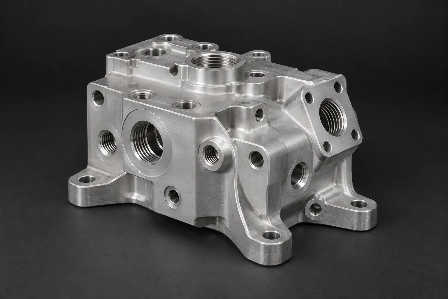
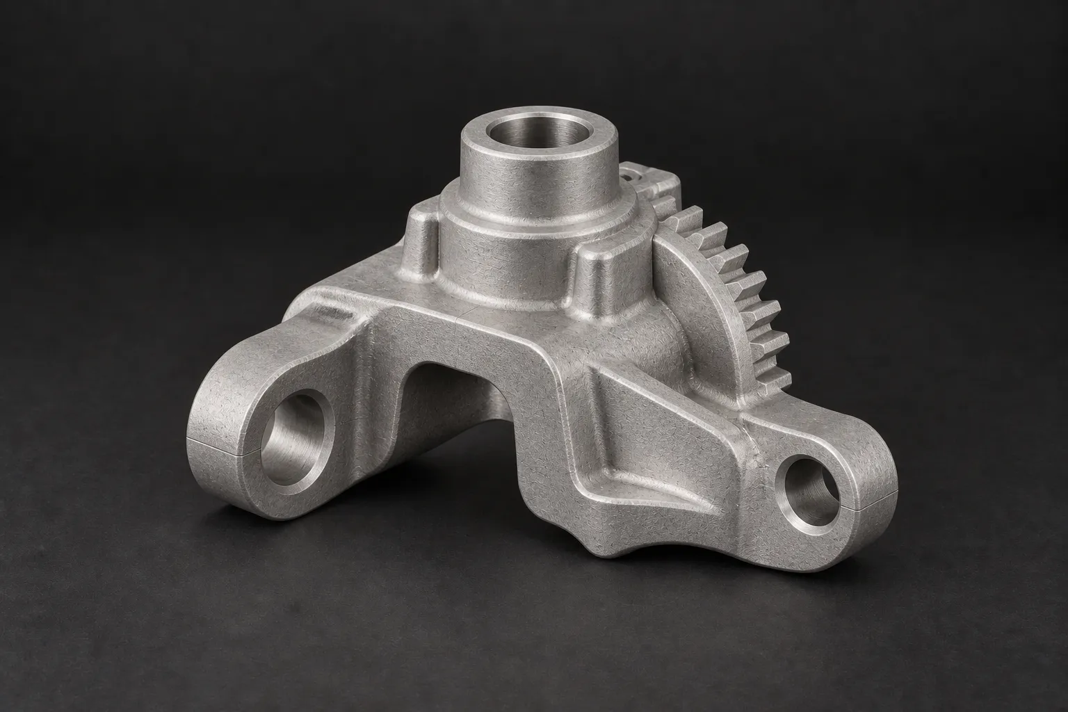
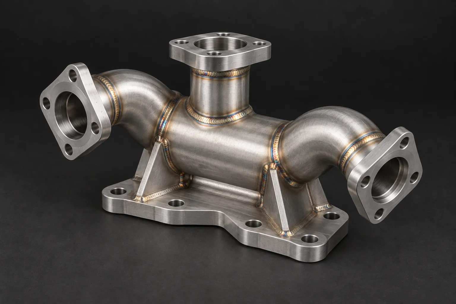
With the model finished, the right process is chosen for the part rather than the part being forced onto whatever machine is free. A worn shaft suits CNC turning. A complex housing that needs accuracy held across several faces suits 5 axis CNC machining. A discontinued plastic component at volume points to plastic injection moulding. A frame may need an agreed welding and assembly route. A bridge part needed while tooling is made can come off a 3D printer first.
Most reverse-engineered parts are made by CNC machining, which is covered in full in the CNC Machining guide. Parts destined for volume production are often better suited to moulding, covered in the Injection Moulding guide. The reverse-engineering work is process-agnostic by design: the model comes first, the process is chosen to suit it.
Stage 9: Inspection and documentation
The finished part is inspected against the CAD model it was made from, not against the worn original. This closes the loop: what you receive matches what was designed, and what was designed was the recovered, corrected definition of the part your machine needs. Critical features are checked, and where the work calls for it a first-article inspection report records the actual measured dimensions against the drawing.
The model and drawing are then retained. From that point on you have an independent, documented source for a part you previously could not buy. Reordering is a reorder, not a fresh reverse-engineering job, and your supply no longer depends on a single sample that could be lost or damaged.
Obsolete and discontinued parts
The single most common reason a part reaches a reverse-engineering shop is that it cannot be bought any more. The machine works. The plant depends on it. One component has gone out of production, and the original maker has either dropped the line, raised the minimum order to an absurd quantity, or closed altogether.
This is a procurement problem dressed as an engineering problem, and reverse engineering solves both halves of it. On the engineering side, the design is recovered and a fitting replacement is made. On the procurement side, the part stops being a single point of failure: once the model exists, the part can be made on demand, in the quantity you need, from a source you control, for as long as the machine runs.
There is a strategic case here that goes beyond the broken part on the bench. An engineer who knows a critical machine relies on an obsolete component does not have to wait for that part to fail before acting. Reverse engineering the part while a good sample still exists, before it wears out, is the difference between a planned replacement and an unplanned line stoppage. The cleanest sample to work from is one that has not yet failed.
Worked examples
The examples below are generic and illustrative. They show how the method plays out on common part types. They are not records of specific customer jobs and carry no specific customer numbers.
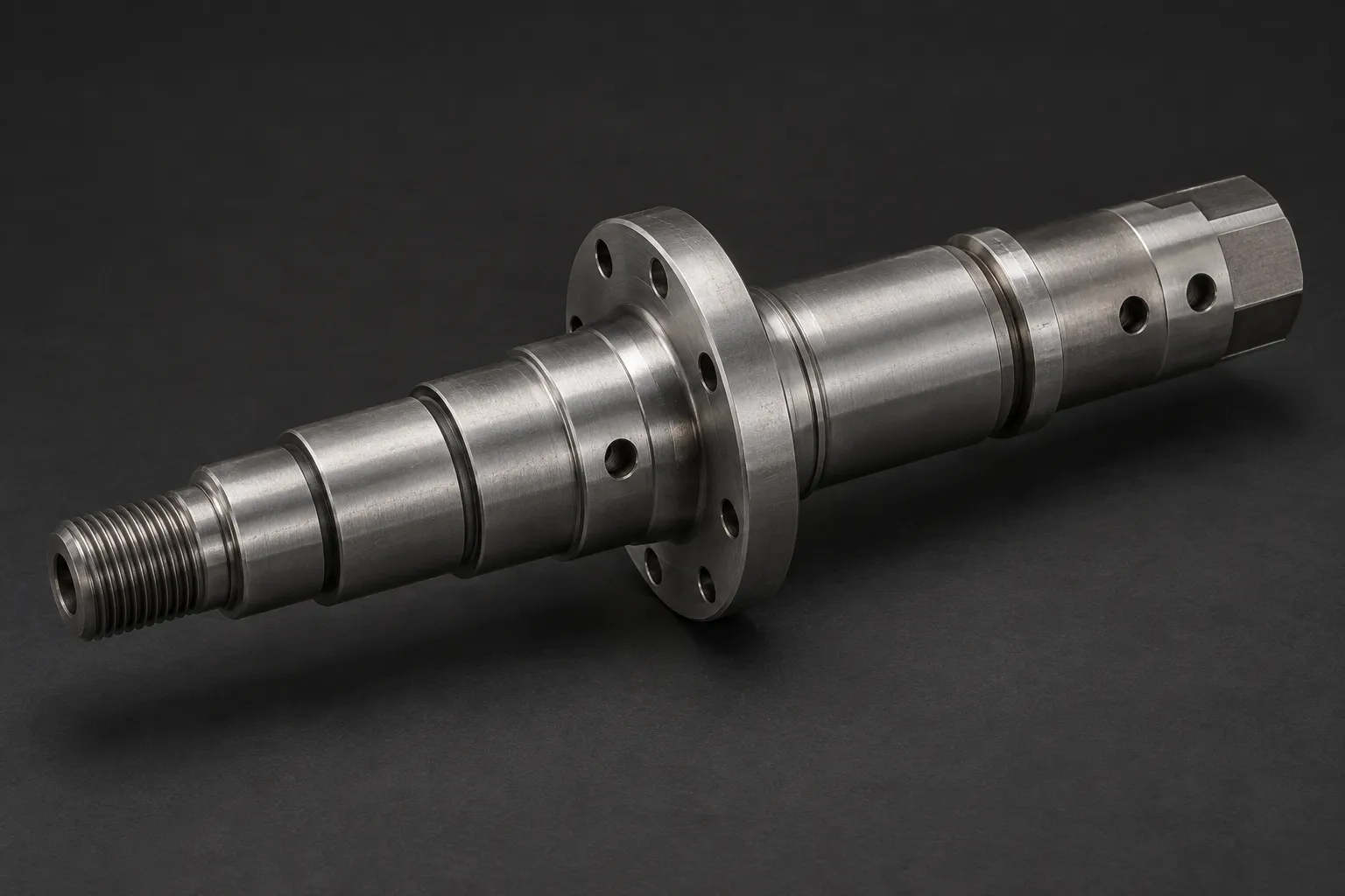
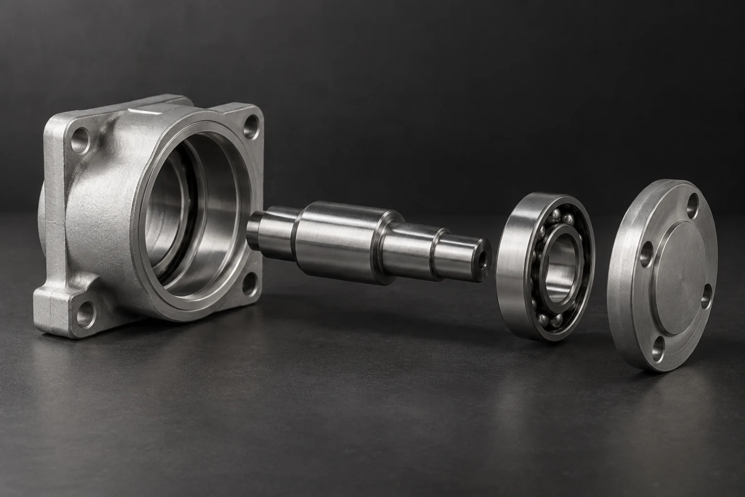
A worn pump shaft. A shaft has worn at the bearing seats and the original drawings are long gone. Metrology records the as-worn diameters, and the as-designed dimensions are recovered by reading the unworn sections, the bearing bore the shaft ran in, and the standard tolerance the seats were designed to. The shaft is rebuilt in CAD, turned from suitable bar stock, and inspected against the model. Where the original wore prematurely, a harder material or a different surface treatment is considered, agreed and applied.
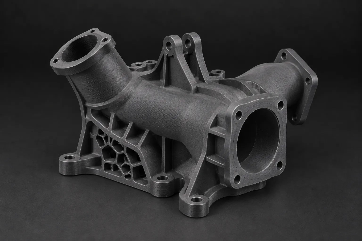
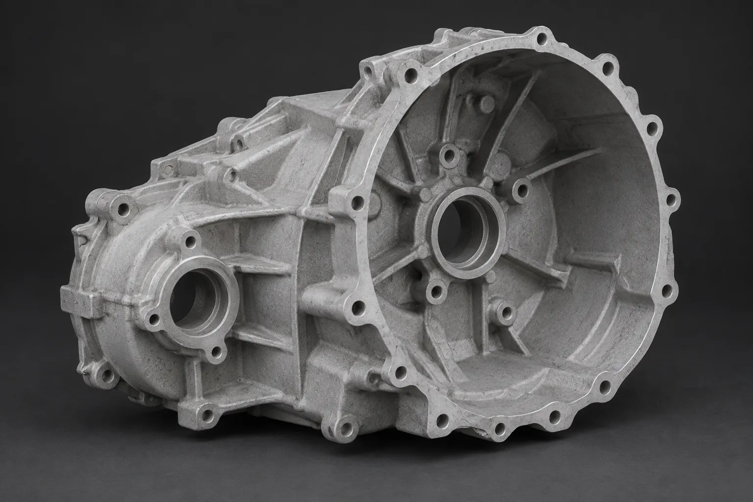
A cracked cast housing. A housing has cracked in service and the failure face shows fatigue beach marks radiating from a sharp internal corner at a sudden change of section. The form is captured by 3D scanning, the critical bores and mating faces by contact metrology, and the part is reconstructed in CAD. The diagnosis is a stress concentration at the corner, so the new design adds a generous fillet radius there. The interfaces are preserved exactly so the part bolts straight back into the machine. The replacement is better than the original at the point that mattered.
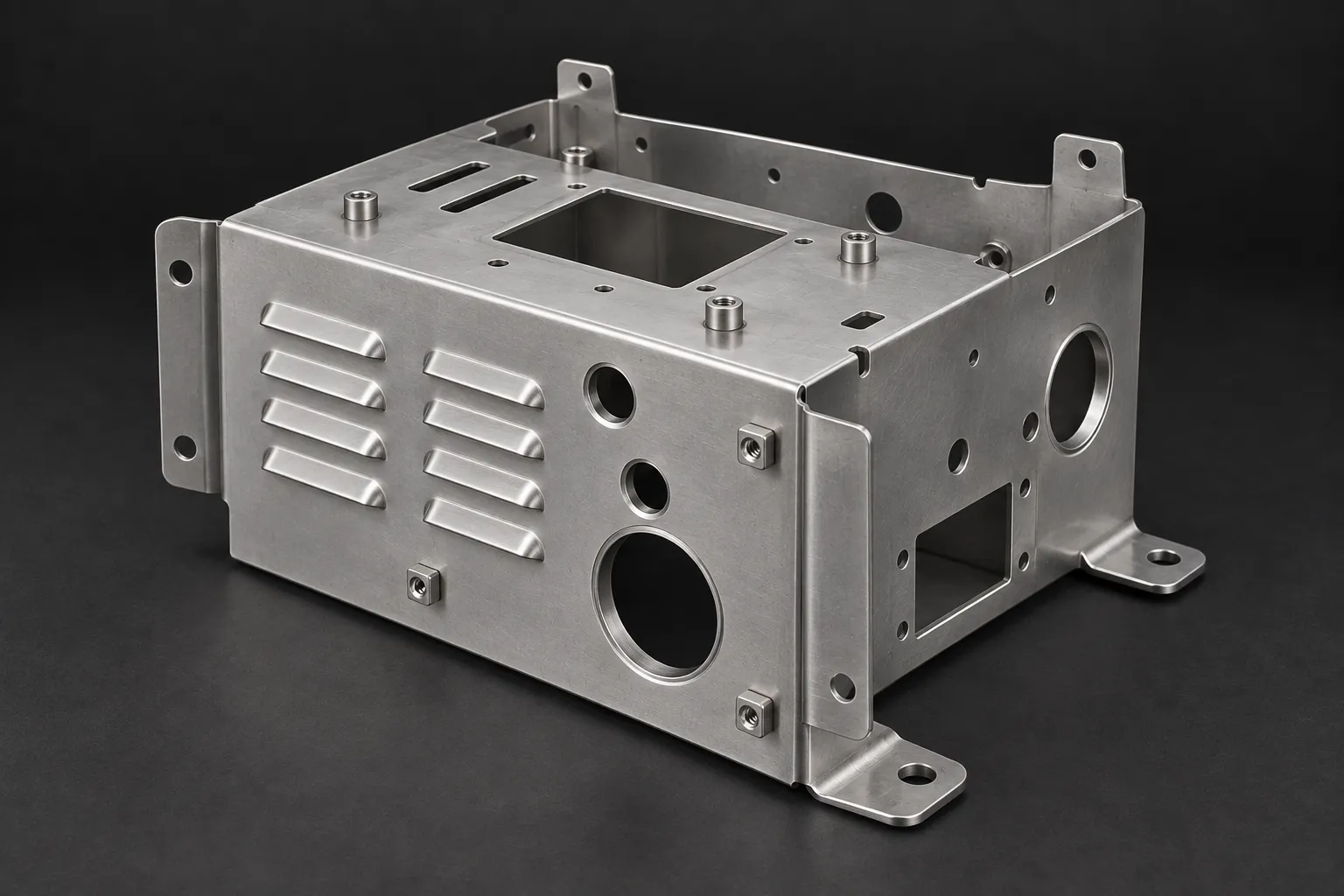
A discontinued bracket. A mounting bracket is no longer available and only one worn example survives. It is a straightforward sheet metal part, so it is measured, its bend allowances and hole pattern reconstructed, and a flat pattern produced for cutting and forming. The model is held on file, and the customer can now reorder one or a hundred whenever needed.
A legacy frame assembly. A welded steel frame for an old machine is needed and nothing remains but the frame itself and a sense of how it sits in the line. The structure is measured, reconstructed as a weldment, and built ready to fit. The reconstruction and manufacturing scope would need to be agreed for the structure and its duty.
How MV does it
Reverse engineering leads MV's work. Our team helps recover a practical manufacturing definition when the available information is incomplete, then plans manufacture around the agreed design. Where evidence supports an improvement, we discuss it before production.
MV brings reverse engineering and manufacturing together around the component's function. Our team reviews the available evidence, agrees the design and selects the supporting process around the job. That may involve 3D scanning, CNC milling, turning or another manufacturing route. We discuss uncertainties before committing them to a finished part.
The full reverse engineering service, including the materials and the eleven manufacturing capabilities behind it, is set out on the Reverse Engineering service page.
What to send us, and how to start
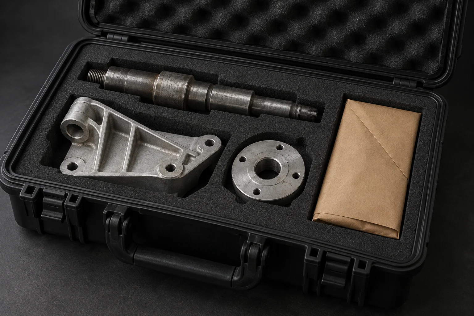
You do not need drawings, and you do not need to have decided the material. Send us the failed, worn, discontinued or obsolete part, a sample, a photograph, any surviving drawings if you happen to have them, or simply a description of what stopped working and what it has to do. The more of the part you can send, even in pieces, the better, but we routinely work from worn and damaged samples.
We will talk through where the part sits, the loads and conditions it works under, the quantity you need and the deadline you are working to, then tell you honestly whether and how we can help. You will have an engineer-made quote within 24 hours.
Send the available component so we can assess whether its design can be recovered and a replacement made. Send us the part.
Related reading: CNC Machining guide · Injection Moulding guide
Start with the part you have
Send photographs, any surviving records and a description of the job. Our Peterborough team will assess the information and recommend the next step.
Discuss your part with MV →Explore reverse engineering · Read the full reverse engineering guide