

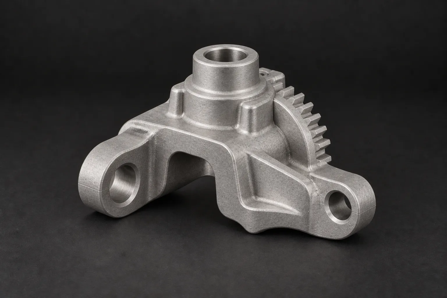
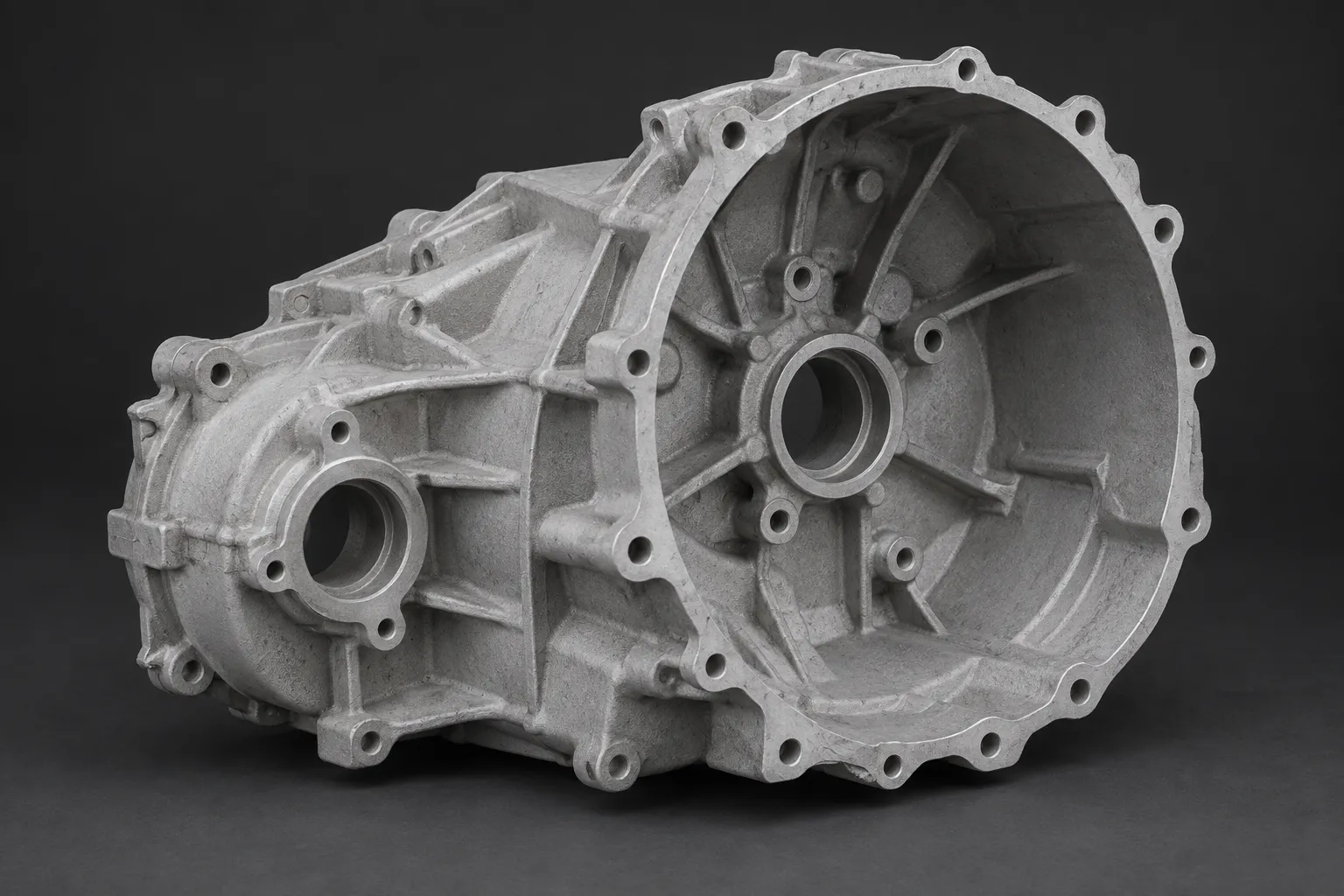
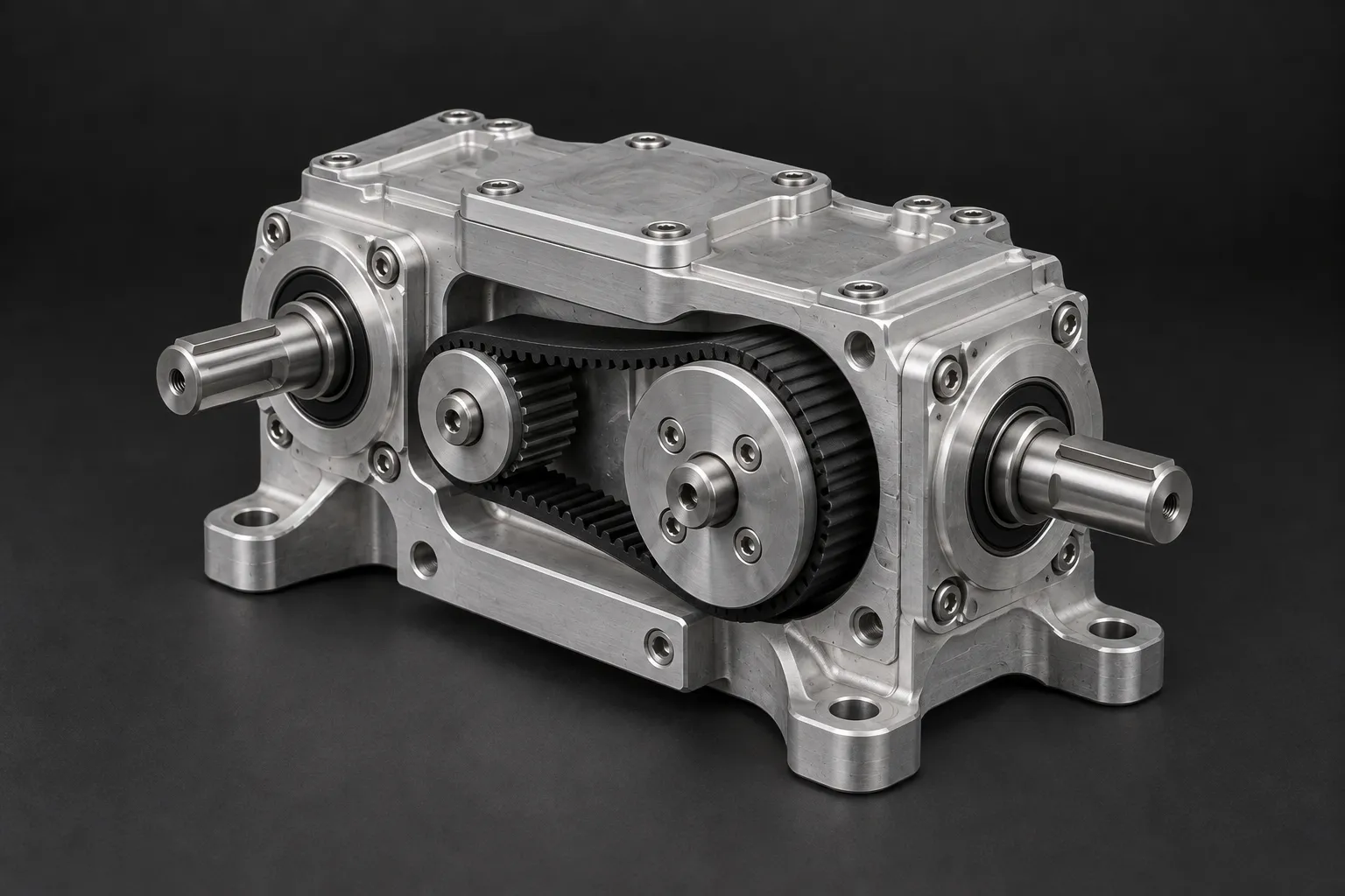
What injection moulding is
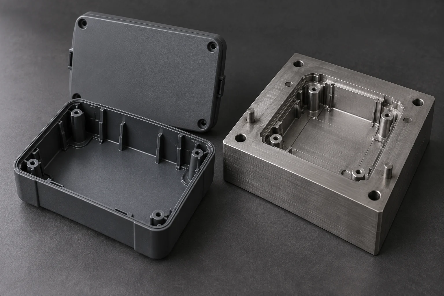
Injection moulding is a process for making the same part many times over. Material is heated until it flows, injected under pressure into a steel tool, the mould, which is a precise negative of the part, then cooled or set until it holds its shape, and the finished part is ejected. The tool then closes and the cycle repeats. A moulding cycle for a typical plastic part takes seconds to a minute or so, which is what makes moulding fast and economical at volume.
The defining feature of moulding, and the one an engineer has to plan around, is the tool. The tool is a significant, one-time cost made before any parts exist, and it is specific to that one part. Everything about moulding economics flows from that fact: the tool is expensive, the parts off it are cheap, and the more parts you make, the less the tool costs per part. Moulding is the right answer when you will make enough parts to spread the tool, and the wrong answer when you will not.
Plastic injection moulding
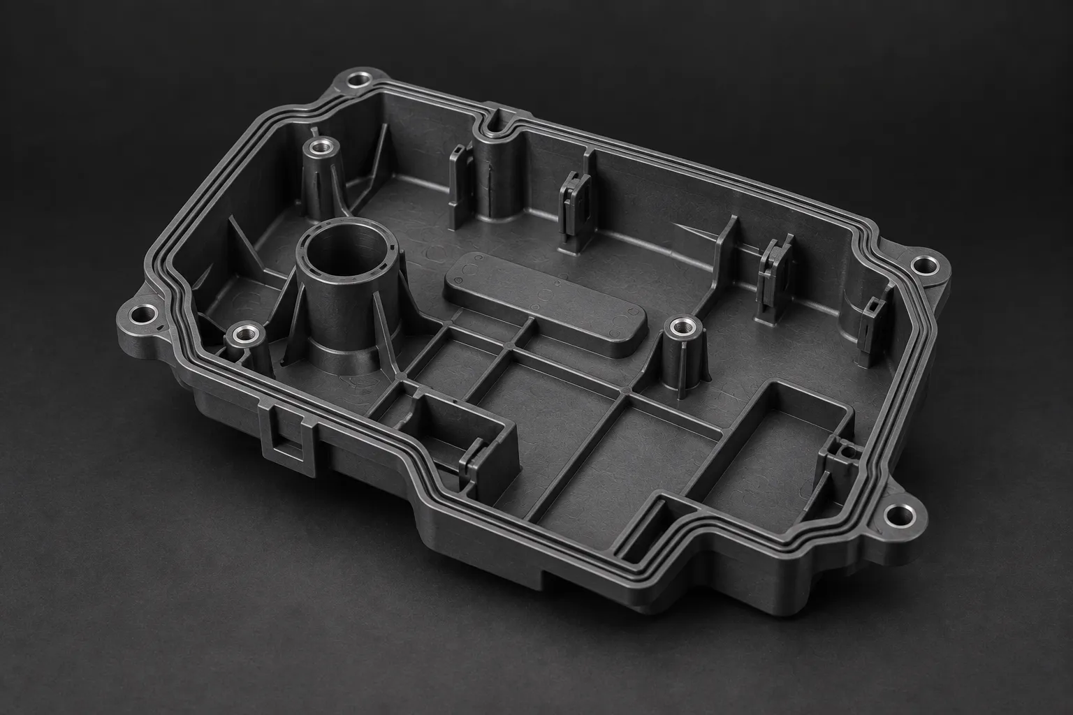
Plastic injection moulding is the common form of the process and the one most parts use. Plastic granules are fed into a heated barrel, melted, and a screw drives the molten plastic into the tool under high pressure. The plastic fills the cavity, packs out as it cools to compensate for shrinkage, solidifies, and the part is ejected.
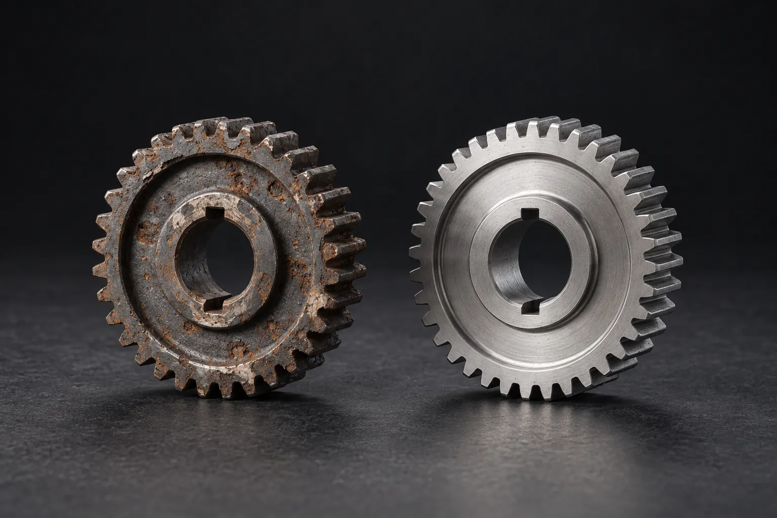
It is the right process for plastic parts in quantity: enclosures, housings, covers, clips, gears, handles, connectors, bushes and the thousands of moulded components inside any machine. The finish off the tool reflects the finish of the tool itself, so a polished tool gives a glossy part and a textured tool gives a textured part, with no secondary operation needed. Detail, text, logos and living hinges can all be moulded directly into the part.
Two behaviours of plastic dominate the design. Plastics shrink as they cool, by an amount that depends on the material, so the cavity is cut slightly larger than the finished part to compensate. And plastics flow and cool best through even wall thicknesses, which is why uniform walls are the first rule of moulding design, covered in section 7.
Metal injection moulding
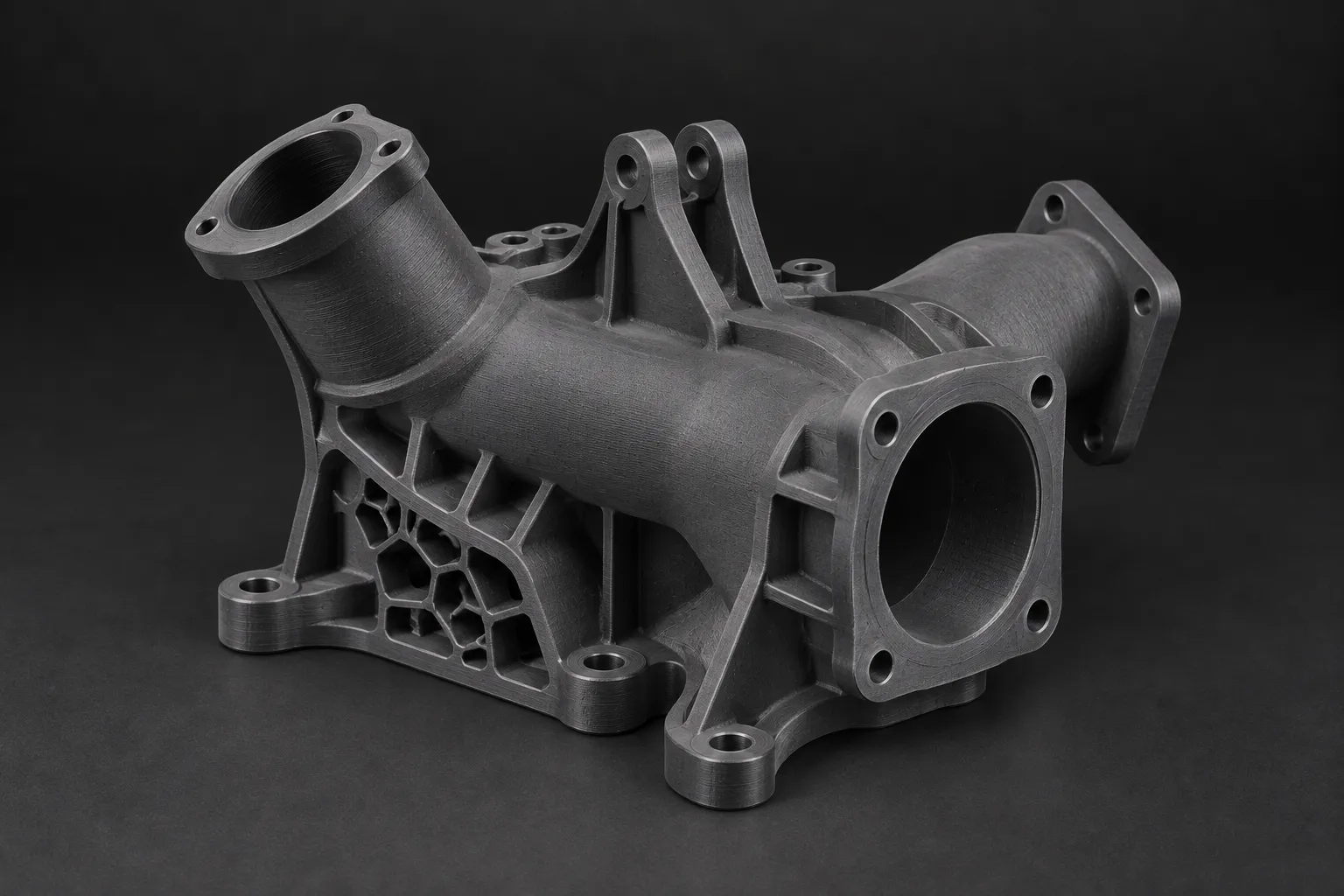
Metal injection moulding, or MIM, applies the moulding process to metal parts. Fine metal powder is mixed with a polymer binder to make a feedstock that flows and moulds like plastic. The part is moulded in the same way as a plastic part, which gives a green part that is metal powder held together by binder. The binder is then removed, and the part is sintered in a furnace, where it is heated until the metal particles fuse and the part densifies into solid metal. The part shrinks substantially and uniformly during sintering, which the tool is designed to allow for.
MIM is the right process for small, complex metal parts in volume, the kind of part that would be slow and wasteful to machine one at a time, where the quantity justifies a tool. Typical MIM parts are small, intricate and produced in large numbers: locks and latches, small gears and levers, surgical and dental components, firearm parts, and complex connectors. It combines the geometric freedom of moulding with the properties of a sintered metal part.
The trade-offs to know: MIM suits small parts rather than large ones, because the powder and sintering economics favour small mass. It needs volume to justify the tool, like all moulding. And the sintering shrinkage has to be controlled, which is part of the process expertise.
Tooling
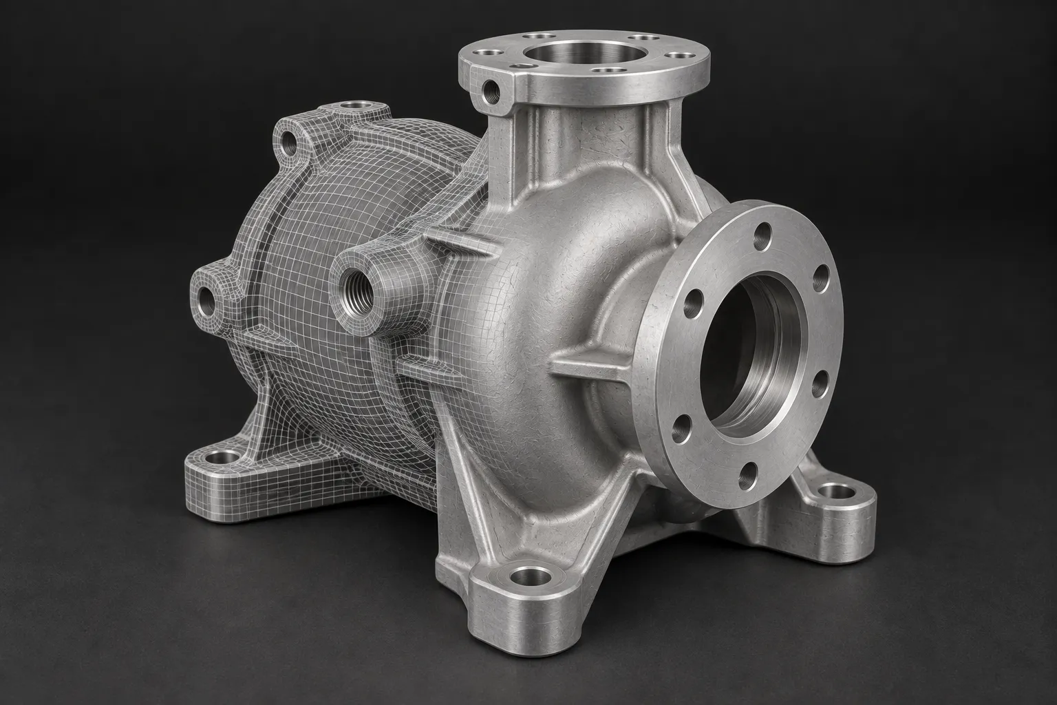
The tool is the heart of a moulding job and the part of it an engineer most needs to understand. A mould tool is a precision-machined steel block, in two or more halves, with a cavity cut into it that is the negative of the part. When the halves close, they form the sealed cavity that the material fills. The tool also contains the runners and gates that channel material into the cavity, the cooling channels that control how the part sets, and the ejector pins that push the finished part out.
A few points shape how an engineer should think about tooling:
- The tool is the main upfront cost. Designing and machining a precise steel tool takes real time and money before a single part is made. That cost is then spread across every part the tool produces, which is the whole logic of moulding economics.
- Tools have a life. A production-grade hardened steel tool can produce a very large number of parts. A lower-cost tool, in aluminium or softer steel, costs less and is quicker to make but wears sooner, which can be the right choice for lower volumes or a bridge run.
- Single versus multi-cavity. A tool can have one cavity or many. A multi-cavity tool moulds several parts per cycle, cutting the cost and time per part, in exchange for a more expensive tool. The right cavity count is a volume decision.
- Tool changes are expensive. Because the tool is cut to the part, changing the part after the tool is made means reworking or remaking the tool. This is exactly why getting the design right before the tool is cut matters so much, and why DFM and, for recovered parts, careful reverse engineering pay off here more than anywhere.
MV sources and manages tooling for production-run parts.
Materials
The material in a moulded part is chosen on the duty, the same as any other part. The notes below describe how common moulding materials behave. Specific grades for a given part are selected against the load, the temperature, the chemical environment and, for a reverse-engineered part, what the original was made from.
For plastic moulding, materials fall broadly into two families:
- Thermoplastics soften when heated and set when cooled, and can be remelted, which is what makes them mouldable. They cover most moulded parts, from commodity plastics to engineering grades such as acetal, nylon, polycarbonate and PEEK that carry real mechanical and thermal load. Fillers such as glass fibre add stiffness and strength to a base plastic.
- Properties to specify against include stiffness and strength, impact resistance, temperature capability, chemical and UV resistance, and whether the part needs to be food-safe, flame-retardant or electrically insulating.
For metal injection moulding, the materials are metal powders, commonly stainless steels, low-alloy steels and other engineering alloys, selected for the strength, hardness and corrosion resistance the part needs, and supplied as a sintered metal part with properties close to wrought metal.
Volumes and when moulding makes sense
Volume is the deciding factor in whether to mould a part at all. Because the tool is a fixed cost paid once, the cost per part is the tool cost divided across the run, plus the small cost of each moulded part. At low volumes the tool dominates and the cost per part is high. At high volumes the tool is spread thin and the cost per part drops to the cost of the material and a few seconds of cycle time.
The general logic, without committing to specific numbers that depend on the part:
- One-offs and very low volumes. Machining or 3D printing is almost always cheaper, because there is no tool to pay for. Moulding a handful of parts means the whole tool cost lands on those few parts.
- Bridge volumes. Where parts are needed before a production tool is ready, 3D printing or machining can bridge the gap, and a lower-cost tool can serve a modest run.
- Production volumes. Once the quantity is high enough that the tool cost per part becomes small against the saving on each part, moulding wins clearly and keeps winning as volume rises.
There is a crossover quantity where machining and moulding cost the same per part, below which you machine and above which you mould. Where that crossover sits depends on the part's complexity, size and material and on the tool cost, which is why it is worked out per job rather than stated as a fixed number. The honest answer to whether to mould a part is almost always specific to that part.
Design for moulding
Design for moulding is a distinct discipline from design for machining, because the constraints are different. A moulded part has to fill cleanly, cool evenly and eject from a steel tool, and those needs drive the geometry. The main rules:
- Uniform wall thickness. This is the first rule of moulding. Even walls fill and cool evenly. Thick sections cool slowly and shrink unevenly, which causes sink marks on the surface and voids inside. Where a part needs to be stiff, ribs are used rather than thick walls.
- Draft angles. The walls of the part that run in the direction the tool opens need a slight taper, the draft, so the part releases from the tool cleanly. A wall with no draft drags on the steel and resists ejection.
- Ribs and bosses. Stiffness comes from ribs, and mounting points from bosses. Both are kept thinner than the wall they join, typically a fraction of the wall thickness, so they do not create a thick section that sinks.
- Radius the corners. Generous internal radii help the material flow, reduce stress concentrations and improve the part, the same principle as in machining and reverse engineering.
- Plan the gate and the parting line. The gate is where material enters and leaves a small witness mark, and the parting line is where the tool halves meet and leaves a faint seam. Both are placed deliberately, away from critical or cosmetic surfaces.
- Avoid undercuts where you can. A feature that traps the part in the tool needs extra tool mechanisms, side actions, to release it, which add tool cost and complexity. Designing them out keeps the tool simpler and cheaper.
Because tool changes are expensive, moulding rewards getting the design right before the tool is cut more than any other process. When a part is reverse engineered for moulding, this design work is done at the CAD reconstruction stage, which is one of the reasons a recovered part can be moulded better than the original. The method is in the Reverse Engineering guide.
Moulding versus machining
The choice between moulding and machining comes down to volume, geometry and material, and it is worth stating plainly because engineers ask it constantly.
Consider machining for prototypes, one-off replacement parts and volumes that do not justify a dedicated mould. Programming, cutting tools and workholding still need to be allowed for. Compare the complete cost of each viable route in the CNC machining guide.
Choose moulding for production volumes of the same part, where the quantity is high enough to spread the tool cost and the saving per part more than repays it. Moulding also produces complex, detailed plastic geometry, with features moulded in, that would be slow or impossible to machine.
For many parts the answer changes over the life of the part. A new part is often machined or 3D printed as a prototype, machined or bridge-tooled for the first low-volume run, then moved to a production mould tool once the volumes justify it. The right process is the one that suits the volume you are at, and it is sensible to plan the transition rather than commit to a tool too early.
How MV approaches moulding
MV offers both plastic injection moulding and metal injection moulding for production-run parts, with tooling sourced and managed on your behalf. Because moulding is a volume process with a real upfront tool cost, the engineering judgement before the tool is cut matters most, and that is where a lean operation with the design done by the people who make the parts is worth most to you.
MV brings reverse engineering and manufacturing together around the component's function. Our team reviews the available evidence, agrees the design and selects the supporting process around the job. That may involve 3D scanning, CNC milling, turning or another manufacturing route. We discuss uncertainties before committing them to a finished part.
Starting a moulding job
Tell us what the part is, what it has to do, the material if you know it, and above all the quantity, because the volume decides whether moulding is the right route at all. Send a CAD model and drawing if you have them. If you have only an existing part and no drawings, the design can be recovered first by reverse engineering, then prepared for moulding. We will tell you honestly whether to mould or machine the part at your volume, and come back with an engineer-made quote within 24 hours.
Related reading: Reverse Engineering guide · CNC Machining guide
Start with the part you have
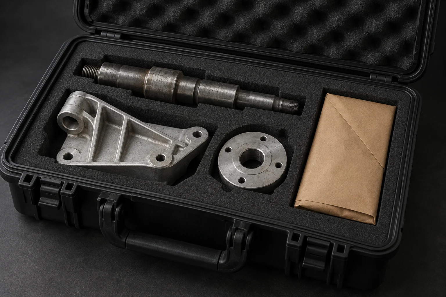
Send photographs, any surviving records and a description of the job. Our Peterborough team will assess the information and recommend the next step.
Discuss your part with MV →Explore reverse engineering · Read the full reverse engineering guide