

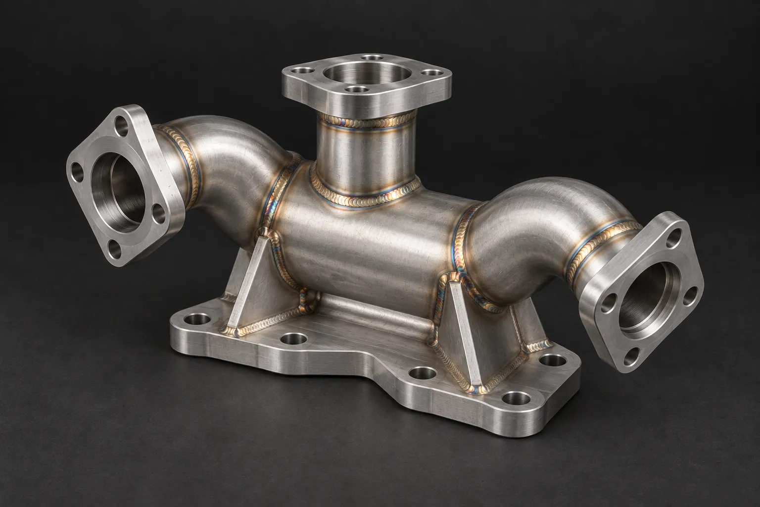
What CNC machining is
CNC machining removes material from stock using programmed cutting tools. CAD describes the geometry and CAM helps plan the toolpaths. The achievable tolerance depends on the feature, material, machine set-up and inspection method. Machining can suit one-off replacements, prototypes and production batches, although cutting tools, fixtures, programming and set-up still contribute to cost.
The two foundational processes are milling and turning. In broad terms, milling spins the tool and holds the part still, and turning spins the part and holds the tool still. Most precision parts are made by one, the other, or both in sequence.
CNC milling
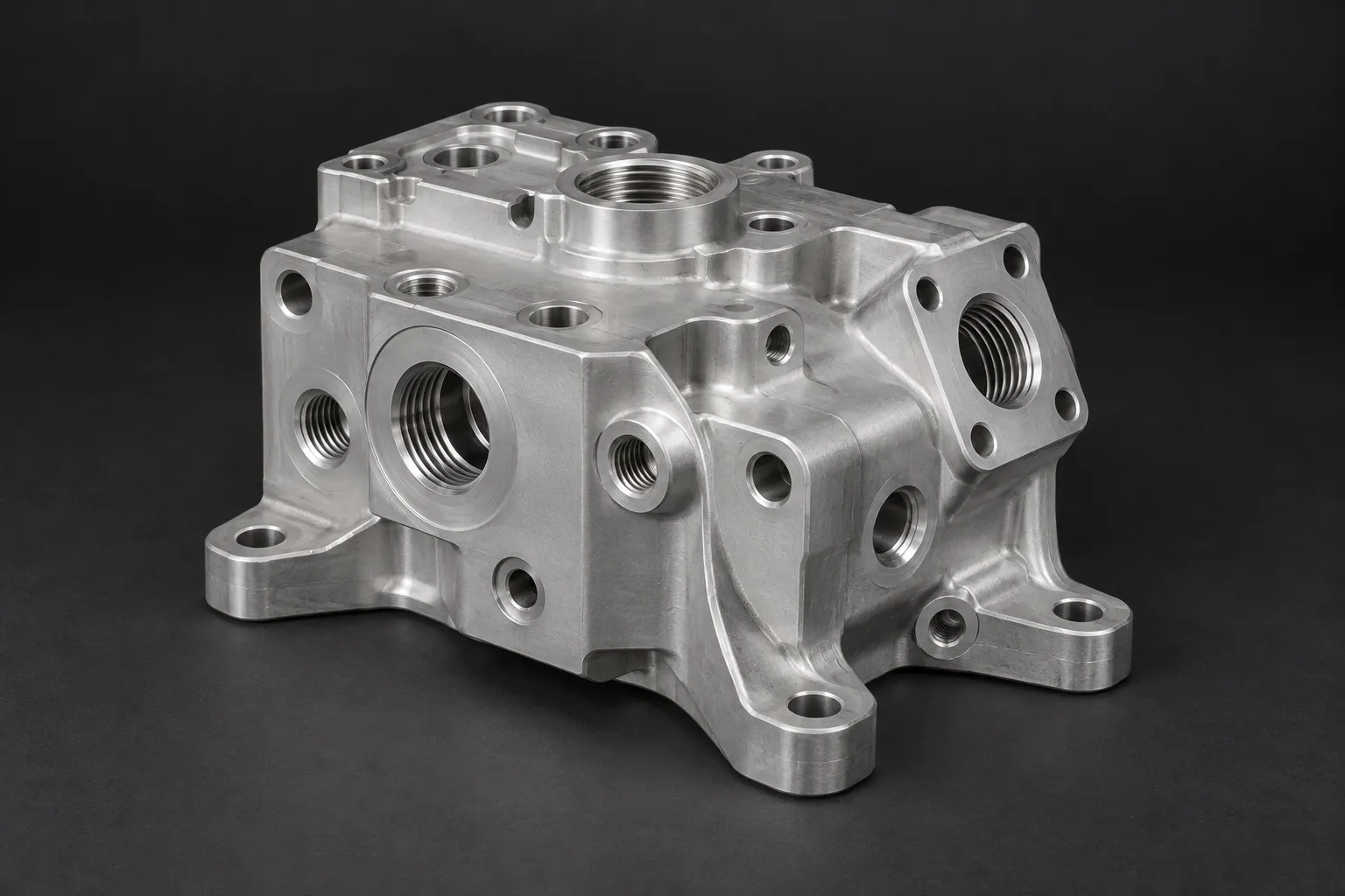
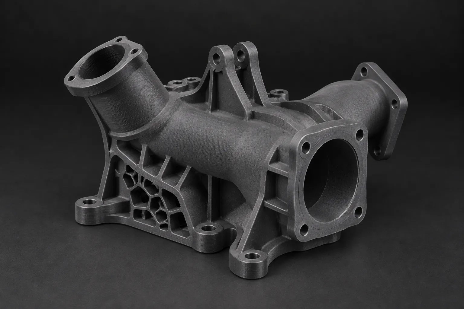
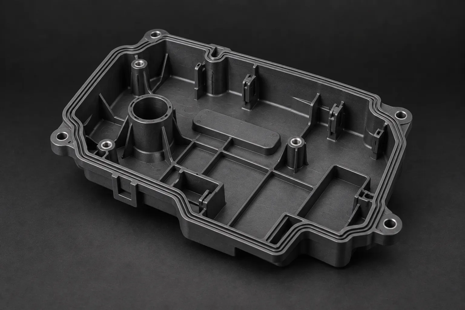
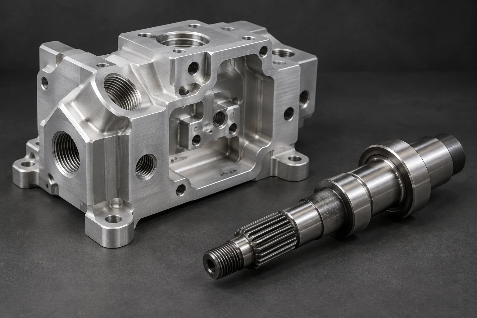
In milling, the workpiece is clamped on a bed and a rotating cutting tool moves against it to remove material. The machine moves the tool, or the bed, along its axes to produce flat faces, slots, pockets, holes, profiles and three-dimensional contoured surfaces. Milling is the process of choice for prismatic parts: brackets, housings, manifolds, plates, mounting blocks, and any component built mostly from flats, pockets and holes.
A milling job is planned around set-ups. A set-up is one clamping of the part in one orientation, and everything the tool can reach in that orientation is machined before the part is moved. Each time the part is unclamped and re-fixtured to reach another face, a small amount of positional accuracy between the features on the two faces is given up, and time and cost are added. Reducing the number of set-ups is one of the main reasons to move from 3 axis to 4 or 5 axis machining, covered in section 4.
Typical milled features and how they behave:
- Pockets and recesses: depth, corner radii and tool access affect how they can be cut.
- Mounting faces: flatness and their relationship to locating features may matter more than appearance.
- Hole patterns: positions need to relate to agreed datums, with thread and counterbore details specified where required.
- Thin walls: stiffness during machining and in service needs consideration before selecting the final geometry.
CNC turning
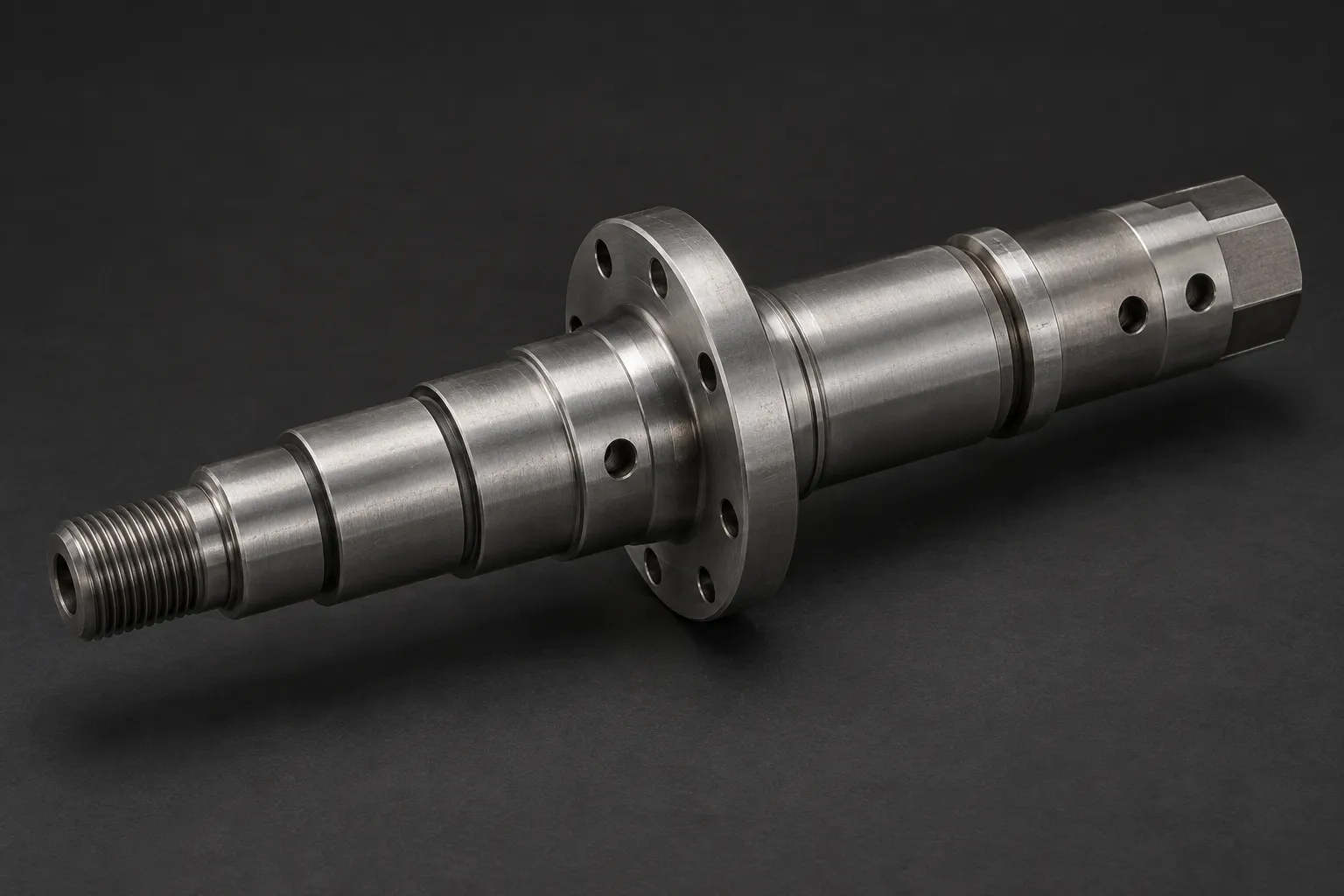
In turning, the workpiece is gripped in a chuck and spun at speed while a stationary cutting tool is fed against it. Turning produces parts that are fundamentally cylindrical: shafts, pins, bushes, rollers, spacers, threaded studs, fittings and housings with a strong axis of rotation. The process is fast and accurate for round features because the rotation itself generates the roundness.
A lathe produces external diameters, faces, tapers, grooves, internal bores and threads, both external and internal. Many modern turning centres also carry driven tooling, which means a small milling spindle inside the lathe can cut flats, slots, cross-holes and keyways while the part is still gripped. This matters because it lets a part that is mostly round but has a few non-round features be finished in one machine, in one set-up, rather than being moved to a mill afterwards. A turned shaft with a milled flat and a cross-drilled hole, complete off a single machine, is more accurate and cheaper than the same part made in two operations on two machines.
Turning behaves differently from milling in a few ways worth knowing. Long slender parts deflect away from the tool and may need a tailstock or a steady rest to support them. Internal bores are limited in depth by the reach and rigidity of the boring bar. And as with milling, internal corners carry a radius left by the tool.
Choosing between 3, 4 and 5 axis
The number of axes describes how many independent directions the machine can move the tool relative to the part at once. It is one of the most common questions an engineer asks, and the honest answer is that more axes are not automatically better, they are better for the right part.
3 axis. The tool moves in three linear directions, X, Y and Z. The part is fixed in one orientation per set-up. 3 axis machining makes the large majority of milled parts well: anything built from one or two faces of flats, pockets and holes. If a part can be reached from above in one or two clampings, 3 axis is usually the right and most economical choice. Its limit is that features on other faces need re-fixturing, and true undercuts or steep angled surfaces cannot be reached at all.
4 axis. A rotary axis is added, so the part can be turned about one axis between or during operations. This lets the machine reach several faces around a part without the operator unclamping and re-fixturing it, which preserves the accuracy between those faces and removes set-ups. It suits parts with features arranged around a central axis: hole patterns around a cylinder, features on the four sides of a block, anything that benefits from being indexed round to a new face under program control.
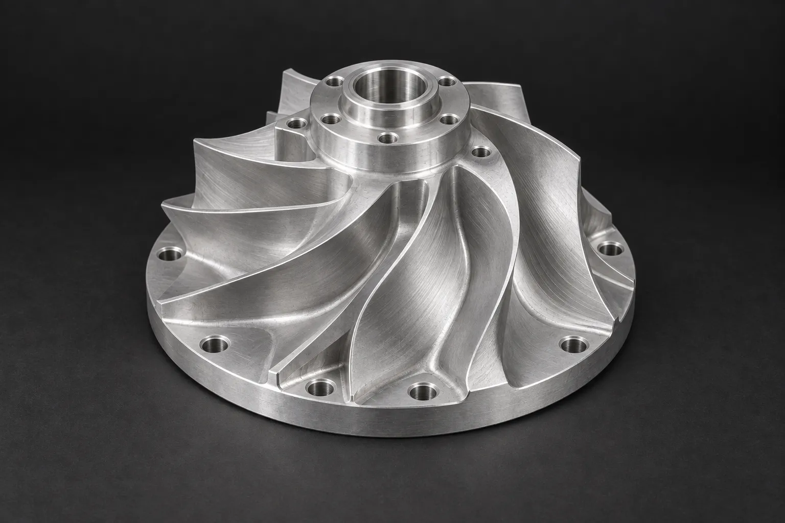
5 axis. Two rotary axes are added to the three linear ones, so the tool can approach the part from almost any angle. The two reasons to choose 5 axis are distinct and worth separating. The first is set-up reduction: a complex part with features on many faces can often be done in a single set-up on a 5 axis machine, which holds the accuracy between all those features and cuts handling time. The second is true 5 axis contouring, where all five axes move together to machine surfaces that simply cannot be reached any other way, such as impeller blades, turbine geometry, angled bores and deep undercut forms. The first reason saves money on parts you could make less efficiently another way. The second makes parts that are otherwise impossible.
The practical rule: choose the fewest axes that make the part correctly in a sensible number of set-ups. A simple plate on a 5 axis machine is wasted capability and wasted money. A many-faced housing on a 3 axis machine is a stack of set-ups, accumulated error and avoidable cost. For a closer look at when complex geometry justifies 5 axis, see the 5 Axis CNC Machining service page.
Materials
CNC machining works across a wide range of metals and engineering plastics, and the material drives the cutting strategy, the speed, the achievable finish and the cost. The notes below are general engineering guidance on how common material families behave under the tool. Specific grades for a given part are chosen on the duty, and where the part is reverse engineered, on what the original was made from and whether it should be matched or improved.
The right material is a duty decision first and a machining decision second. A part that runs hot, carries fatigue load or lives in a corrosive medium is constrained by its environment, and the job is to pick the most machinable grade that still meets the duty.
Surface finishes and treatments
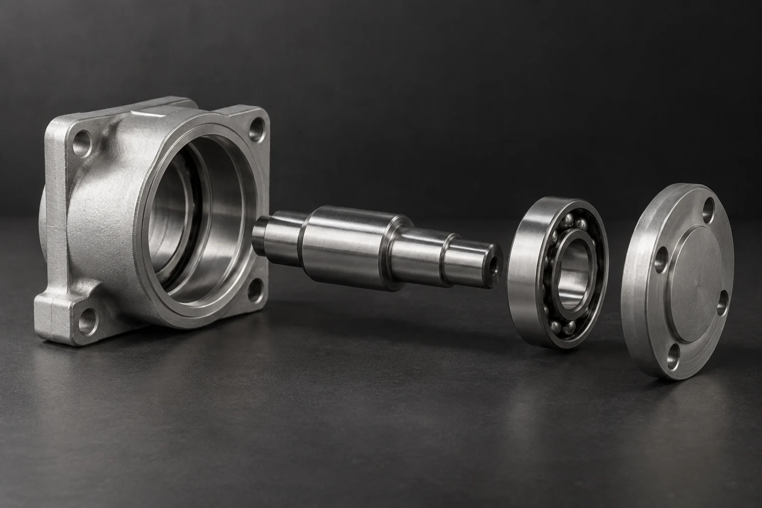
A part comes off the machine with an as-machined finish, carrying fine tool marks. For many components that is exactly what is wanted. Where it is not, the finish is improved by the machining strategy itself, a finishing pass at high speed and light cut, or by a secondary process applied after machining. Common options and what they are for:
- As-machined: suitable where the agreed surface requirement can be achieved directly during machining.
- Bead blasting: creates a more uniform appearance; critical surfaces and dimensional effects need consideration.
- Anodising: an option for suitable aluminium alloys, with coating requirements and mating dimensions agreed beforehand.
- Plating or other protective coatings: selected around the material, operating environment and required properties.
- Grinding or other finishing operations: considered where the specified geometry or surface requirement calls for a separate process.
Finish and tolerance interact. The tightest tolerances and the smoothest finishes cost more, so they belong only on the features that need them. A bearing seat earns a fine finish and a tight tolerance. The outside of the same housing usually does not.
Tolerances and what drives them
A tolerance is the allowable variation on a dimension, and it is the single biggest driver of cost on a machined part after the material and the geometry. Tighter tolerances need slower cuts, finishing passes, better fixturing, more measurement and sometimes temperature-controlled conditions. Specifying a tight tolerance where a loose one would do adds cost for nothing.
The discipline is to tolerance the function, not the whole part. The features that determine whether the part works, the bearing seats, the mating faces, the sealing diameters, the hole positions that locate it, carry tight tolerances because the function depends on them. The features that only have to be roughly right carry a general tolerance. A drawing that calls a tight tolerance on every dimension tells the machinist nothing about which features actually matter and forces unnecessary cost across the part.
MV does not publish a blanket tolerance figure, because the achievable tolerance depends on the feature, the material, the size of the part and the process. The right tolerance for each critical feature is established at quote stage, against what the part has to do.
Design for manufacture
Design for manufacture, or DFM, is the practice of designing a part so that it is sound to make as well as sound to use. A part can be perfectly correct on the drawing and still be slow, expensive or risky to machine. Good DFM removes that gap, and most of it comes down to a handful of habits.
The strongest DFM happens as a conversation before the part is cut, not as a list of corrections after. When MV reverse engineers a part, DFM is applied at the reconstruction stage, which is one of the ways a reverse-engineered part can come back better than the original. The full method is in the Reverse Engineering guide.
How MV approaches CNC work
CNC machining, across milling, turning and 5 axis work, is the biggest part of what MV makes and the process behind most reverse-engineered parts. MV makes single replacement parts and prototypes as readily as production batches, and chooses the process and the number of axes to suit the part rather than forcing the part onto one machine.
MV brings reverse engineering and manufacturing together around the component's function. Our team reviews the available evidence, agrees the design and selects the supporting process around the job. That may involve 3D scanning, CNC milling, turning or another manufacturing route. We discuss uncertainties before committing them to a finished part.
Starting a CNC job
Send a CAD model and a drawing if you have them, with the critical dimensions and tolerances marked. If you have no model, send the part or a sample and the design can be recovered first, which is reverse engineering. Tell us the material if you know it, the quantity, the finish and the deadline. We will come back with an engineer-made quote within 24 hours, and with any DFM points that would make the part better or cheaper to produce.
Related reading: Reverse Engineering guide · Injection Moulding guide
Start with the part you have
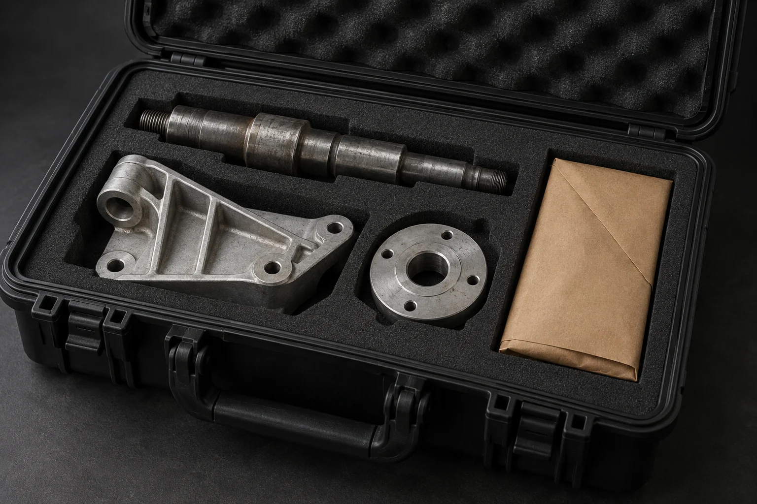
Send photographs, any surviving records and a description of the job. Our Peterborough team will assess the information and recommend the next step.
Discuss your part with MV →Explore reverse engineering · Read the full reverse engineering guide