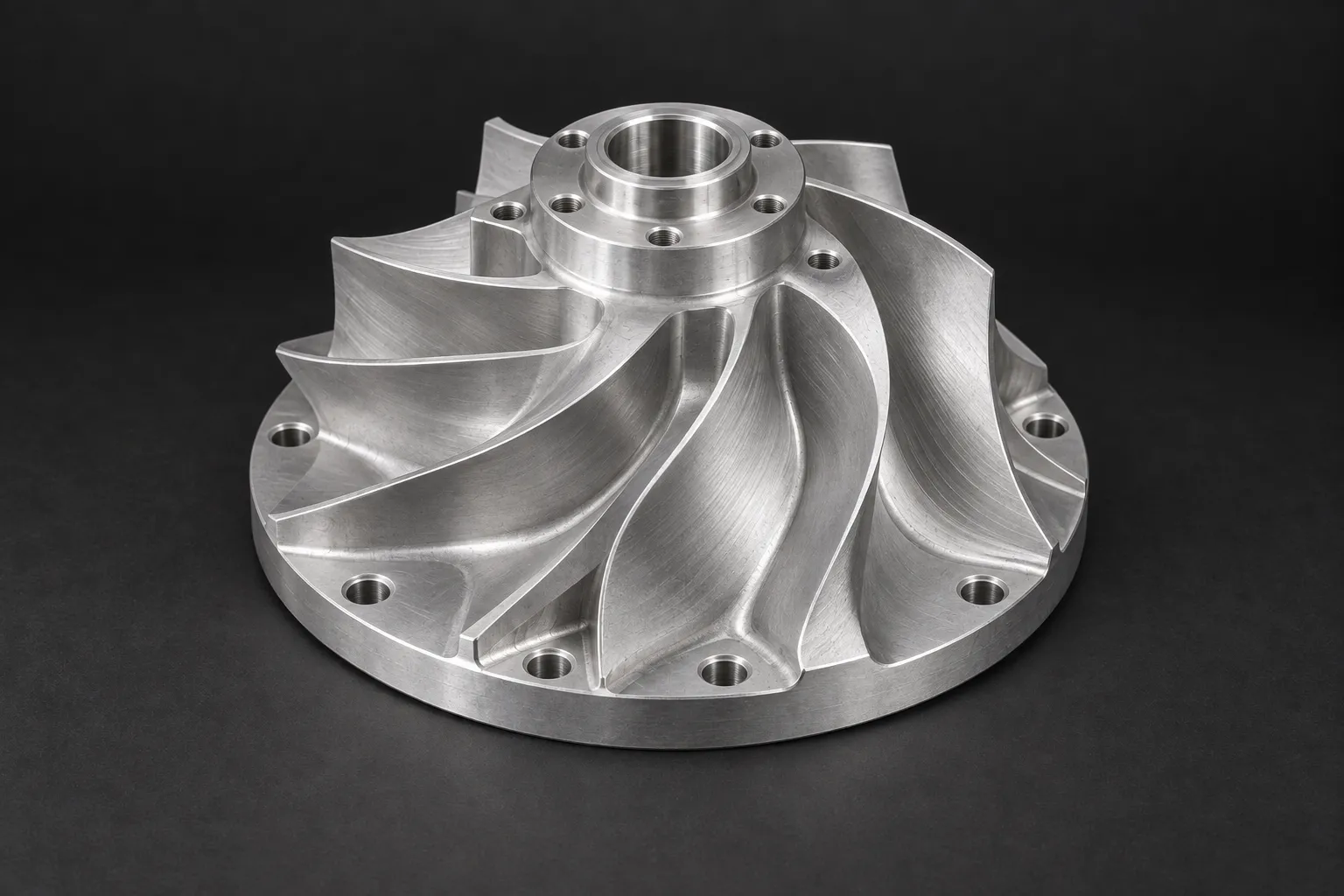
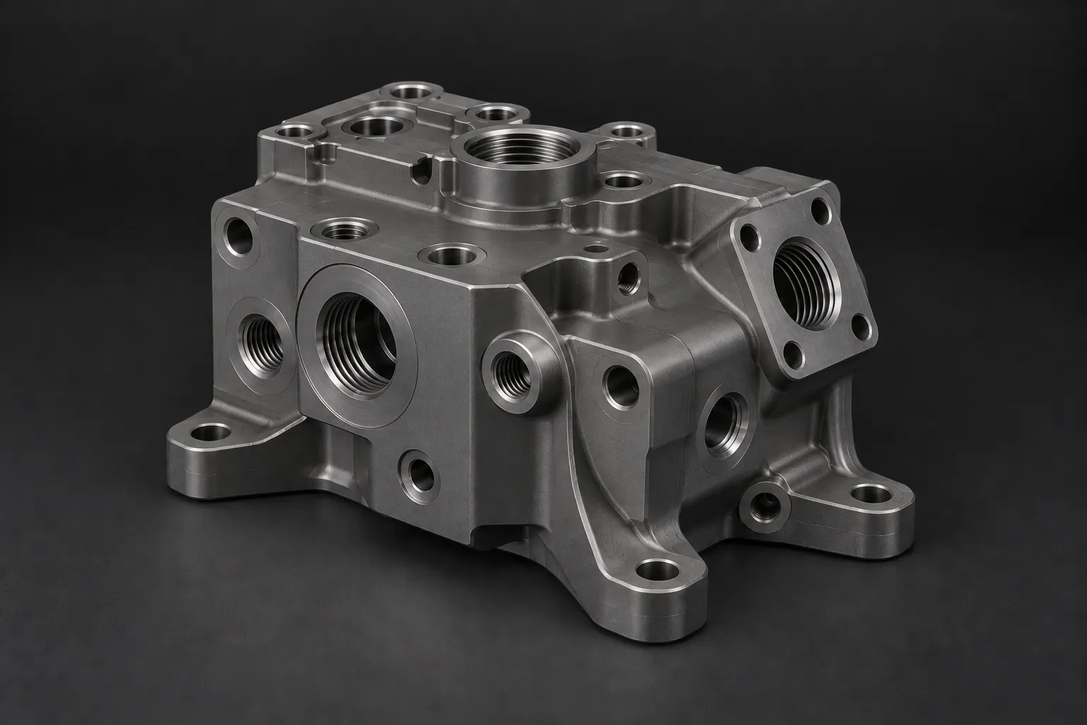
Complex geometry cut in one setup, by engineers who have made the part before. Five faces reached in a single fixturing, so angled features, contours and deep pockets stay true to one another, typically held to around 0.05mm or tighter on request. Work from your CAD and drawing, or from a worn sample we reverse engineer first. A real engineer prices it within 24 hours.
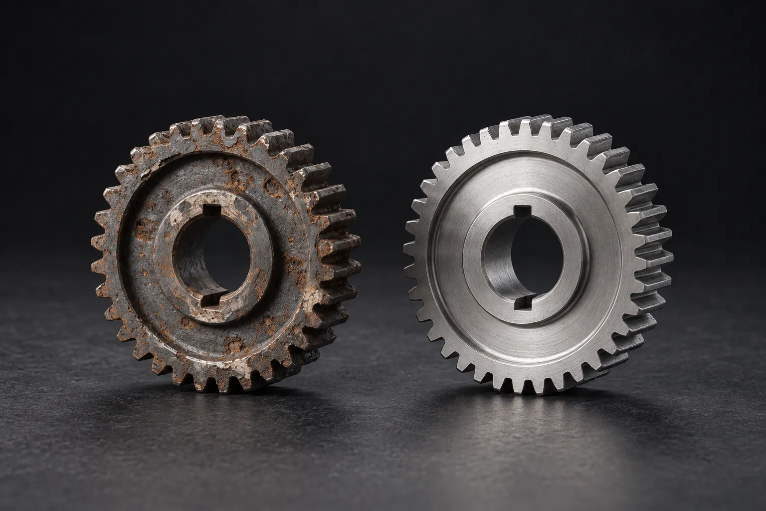
Start with a worn, failed or discontinued part. We reconstruct the design and agree improvements before manufacture.
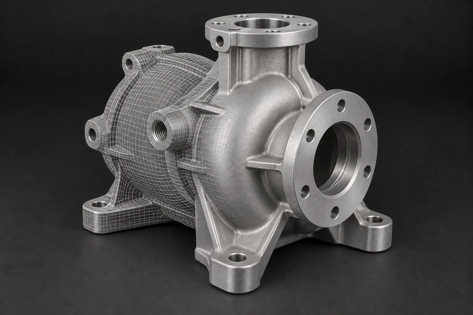
Digital surface capture to support CAD reconstruction and the wider reverse engineering job.
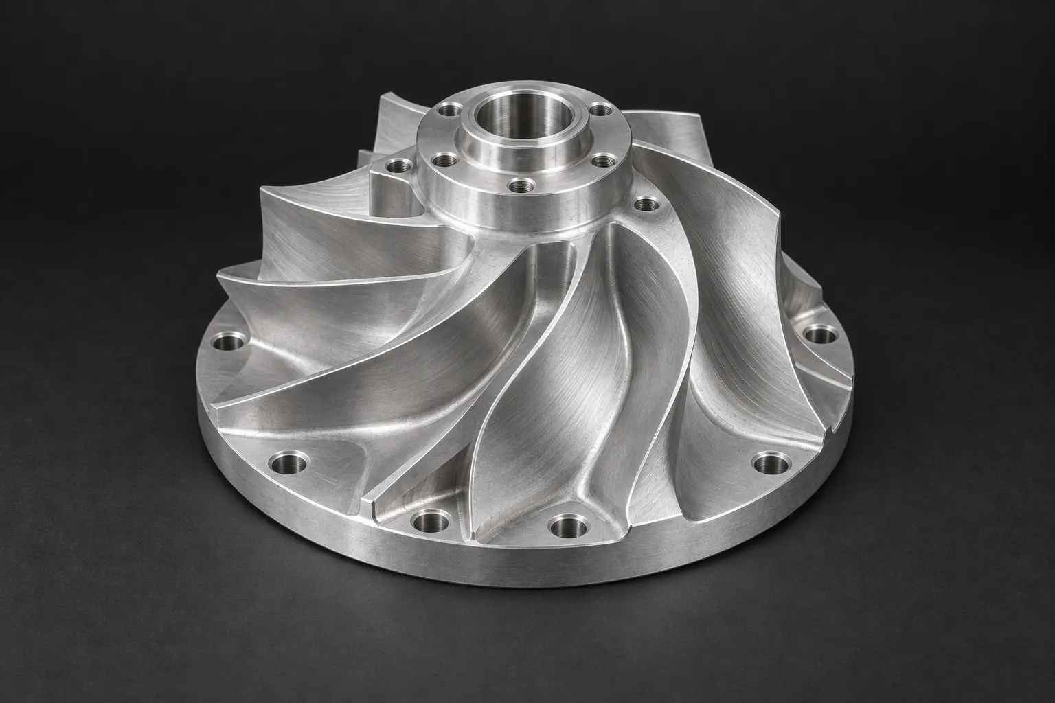
Machine angled features and complex surfaces, with the set-up planned around the critical relationships.
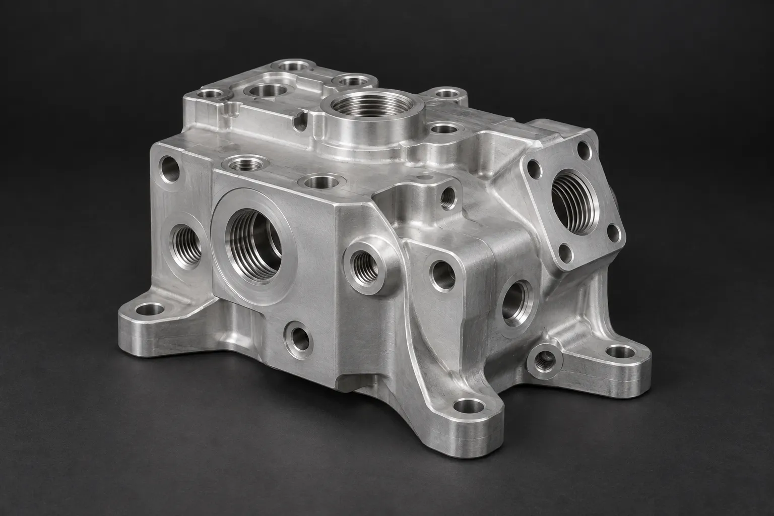
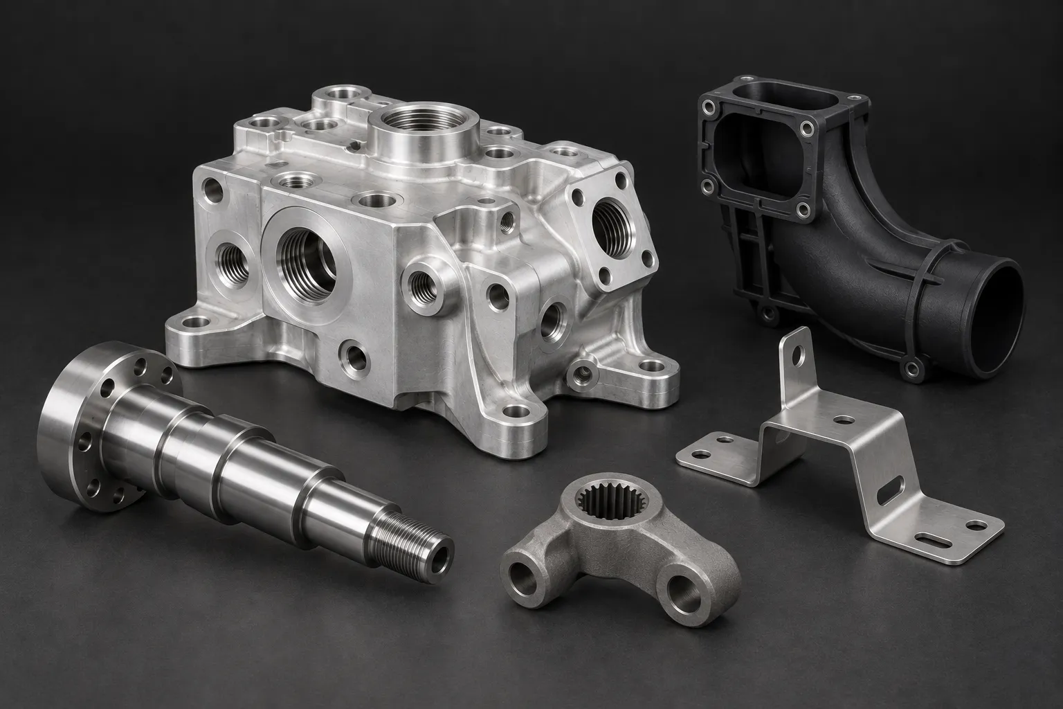
Milled housings, brackets and precision components in metals and engineering plastics.
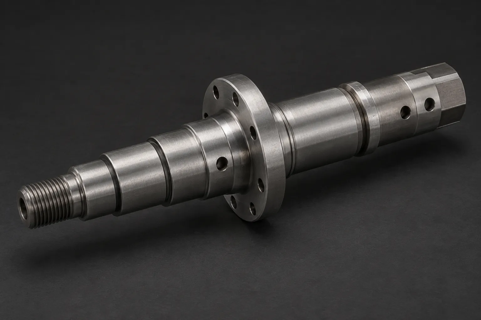
Stepped shafts, threaded fittings and housings, made to drawing or reverse engineered from a sample.
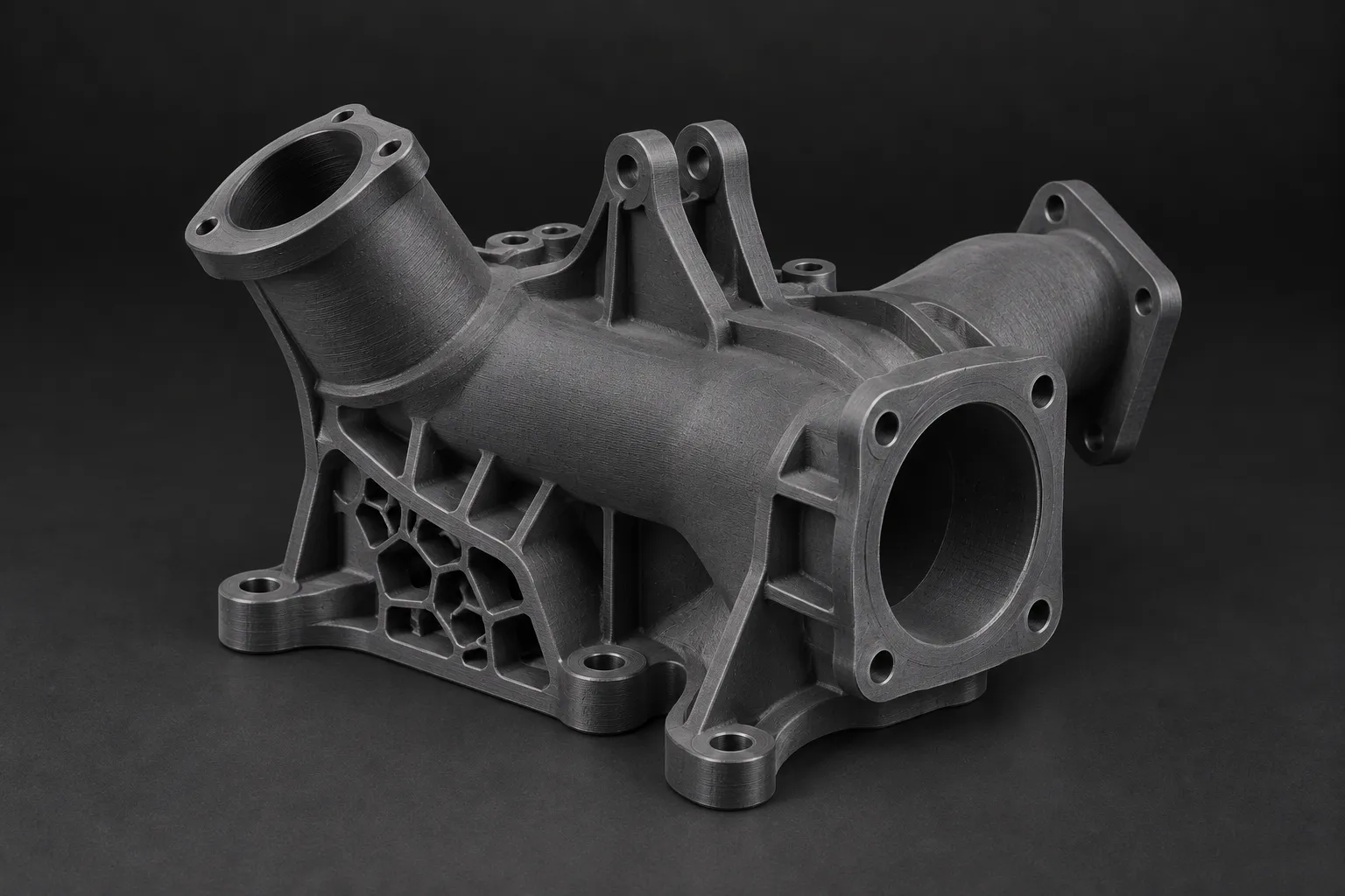
Bring us the application. Our engineers recommend the material and approach for your prototype or part.
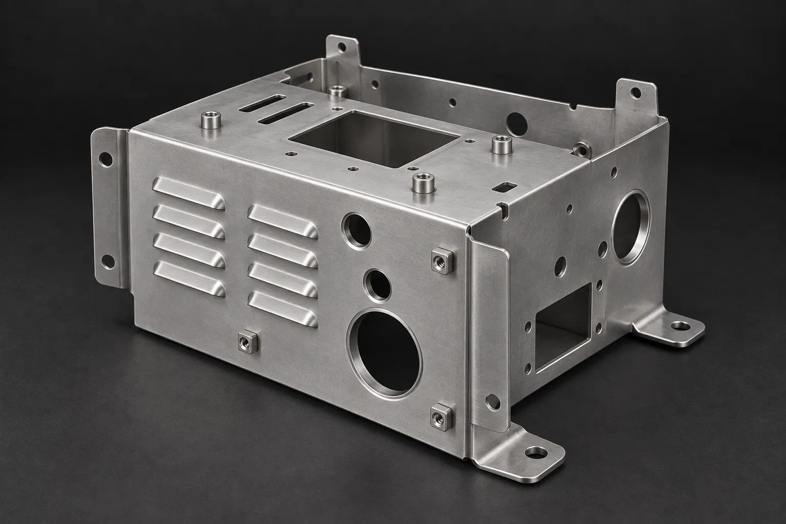
Brackets, panels and enclosures, developed around the bends, interfaces and finished assembly.
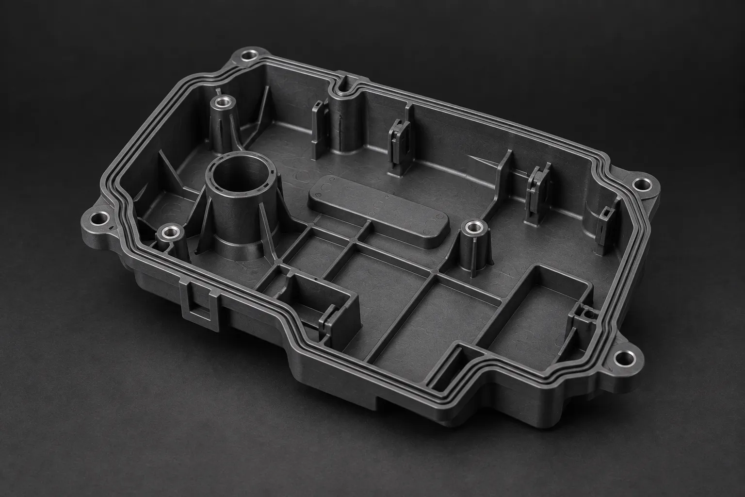
Moulded plastic components, with material, tool design and production requirements considered together.
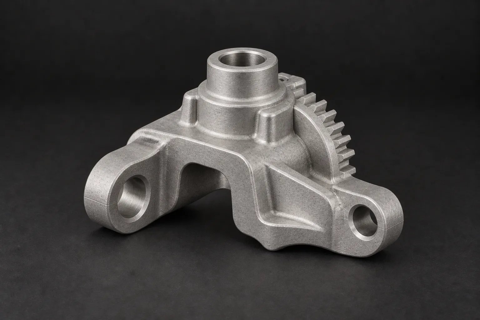
Small, complex metal components where geometry and quantity suit moulding and sintering.
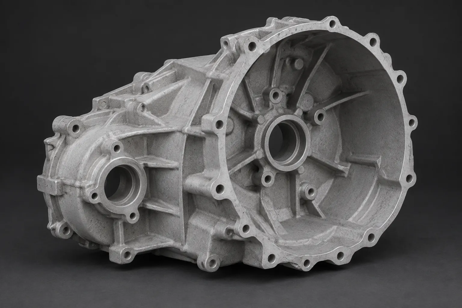
Aluminium housings and components, with casting geometry and any secondary machining planned together.
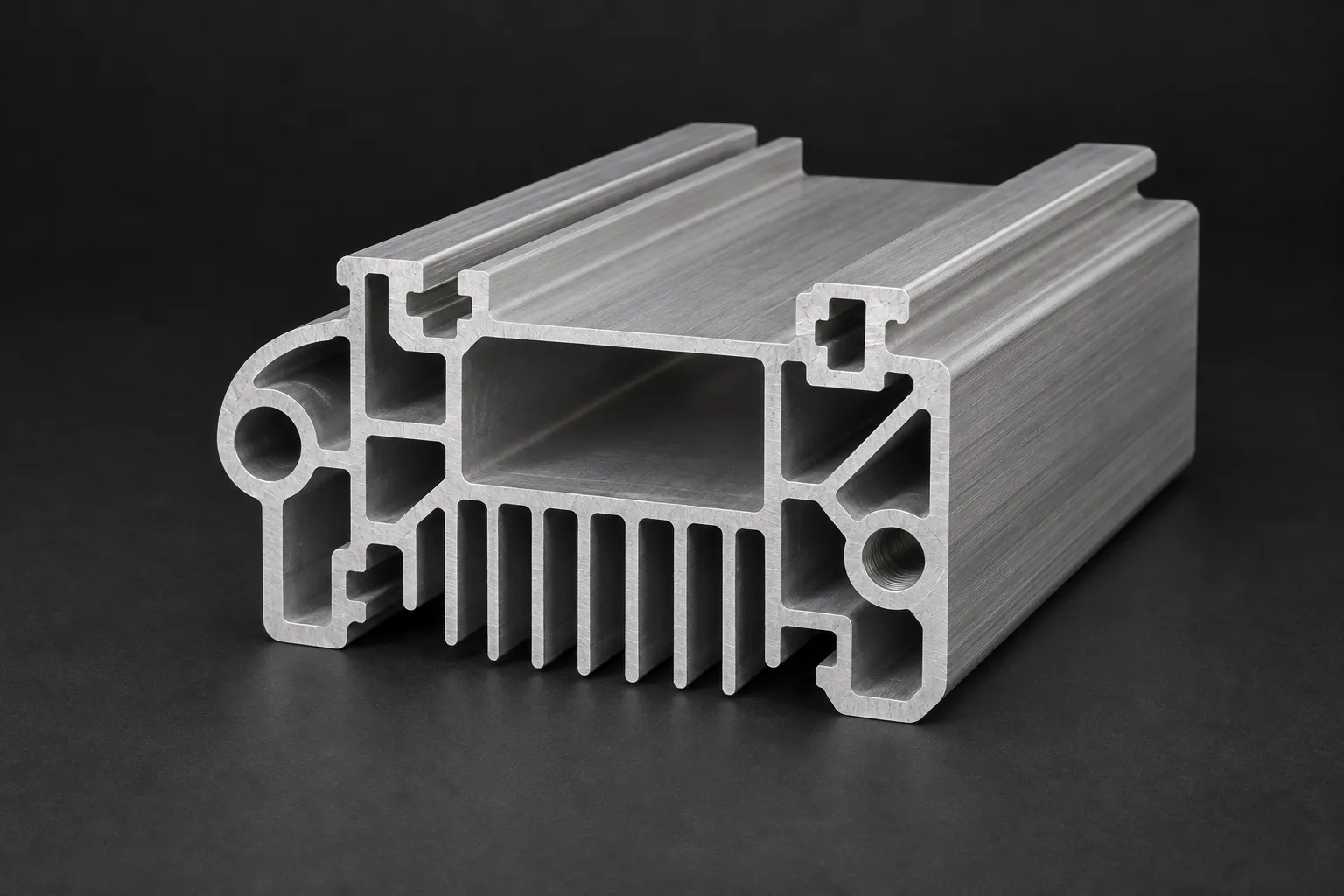
Custom sections developed for the application, then cut, machined and finished as required.
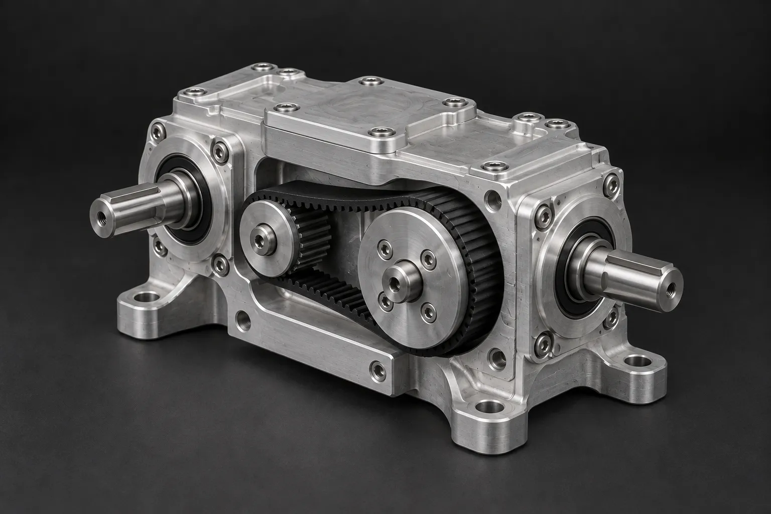
Manufactured and bought-in components brought together, with the interfaces and checks agreed first.
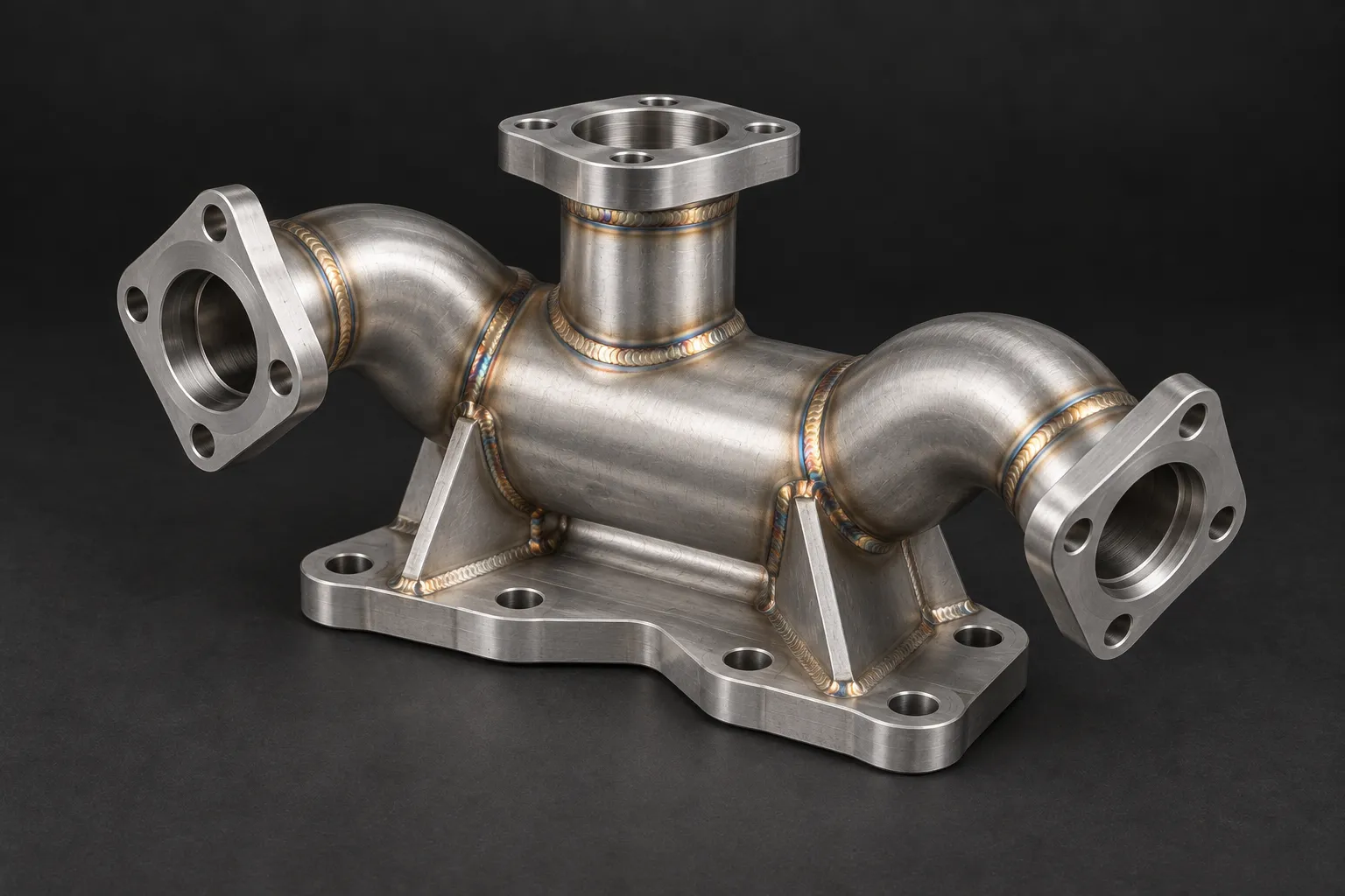
Welded components and fabrications, planned around material, joint access and distortion control.
5 axis CNC machining moves a cutting tool along three linear axes and rotates the part or the tool head on two more, so the machine can reach five faces of a component in a single setup, cutting angled features, contoured surfaces and deep pockets without re-fixturing by hand. Fewer setups means fewer chances to introduce error: a part that would take four or five operations on a 3 axis machine is often finished in one, holding its form and the relationship between its features because nothing is unclamped and clamped again. That is why it suits tight-tolerance parts with several critical faces, typically held to around 0.05mm or better, and why we prove the first article against the CAD model before a run continues.
Five faces cut in a single setup, so every feature stays true to the others.
Contoured and freeform surfaces, angled bores and undercuts a 3 axis pass cannot reach.
Work from your CAD and drawings, or from a worn sample we reverse engineer first.
Aluminium, steel, stainless steel and engineering plastics. Tell us the grade to confirm.
A complex part with features across several faces still has one set of datums holding it together. We measure the sample, rebuild it in CAD with those relationships intact, and machine the replacement in a single setup, correcting the fault the original carried.
Bring us the worn or failed part with no paperwork. We measure it, rebuild the model and machine the replacement on five axes from there.
Because five faces are cut without re-fixturing, the datum is held across every feature, so a part that has to stay true from face to face comes off right.
We machine on our own equipment and through a bank of trusted partners, so we can produce exactly what the part needs, in the right material and to the right tolerance, rather than fitting the job to one machine.
Please see our material lists for 5 Axis CNC Machining. Looking for a material you can’t find here? Get in touch to discuss your requirements.
Al6061
Al6063
Al6082
Al7075 (Aerospace Grade)
Al5086 (Marine Grade)
Al5754 (H22)
1045 (EN8 / C45)
EN24
EN19
303
304
306
316
Duplex 2205
Titanium Ti-6Al-4V (TC4)
Titanium TA2
Bronze C510, C544
Brass CZ121, CZ112 / CW712R
Alloy Steel 4340
Copper C101, C172
Copper C14500 / CW118C
Nickel Inconel 625, 718
ABS
PP
POM-M
POM-C
HDPE
PEEK
PPS
PPSU
Complex 5-axis machined parts take the same finishing options as our standard machining service, since the finish is applied after the part has been cut. As machined, bead blasted, and anodised in either Type 2 colour or Type 3 hard coating are all available as standard. Let us know if you need a finish that is not listed and we will check whether we can source it.
Surface roughness can be specified using Ra value.
Ra3.2 - 1.6um as standard.
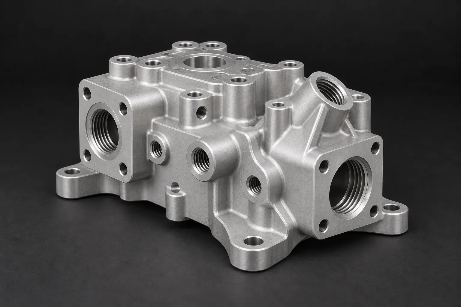
Bead blast size: 80um as standard. 50-120um available.
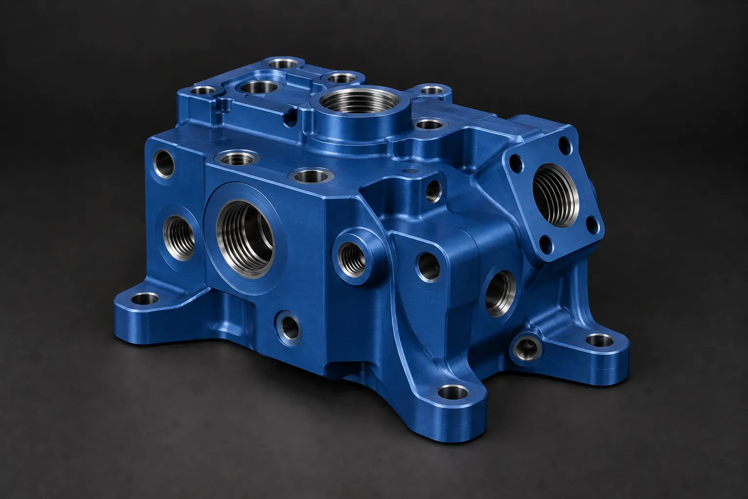
Standard: Clear / natural, black, red, green, blue, yellow / gold. Close match to specified RAL numbers.
Standard: Black or Grey. Much duller in look, but has much better surface protection.
We sell the expertise that gets a complex part right in one setup, not machine time. That means the CAM planned to protect the critical features, the datum held across every face, and the first part proven against the model before the run continues. Over 100,000 parts delivered, on time or early every time, stand behind that judgement. Our engineering team plans the work together, with one point of contact keeping the job clear and coordinated. Here is what that means when you send us 5 axis work.

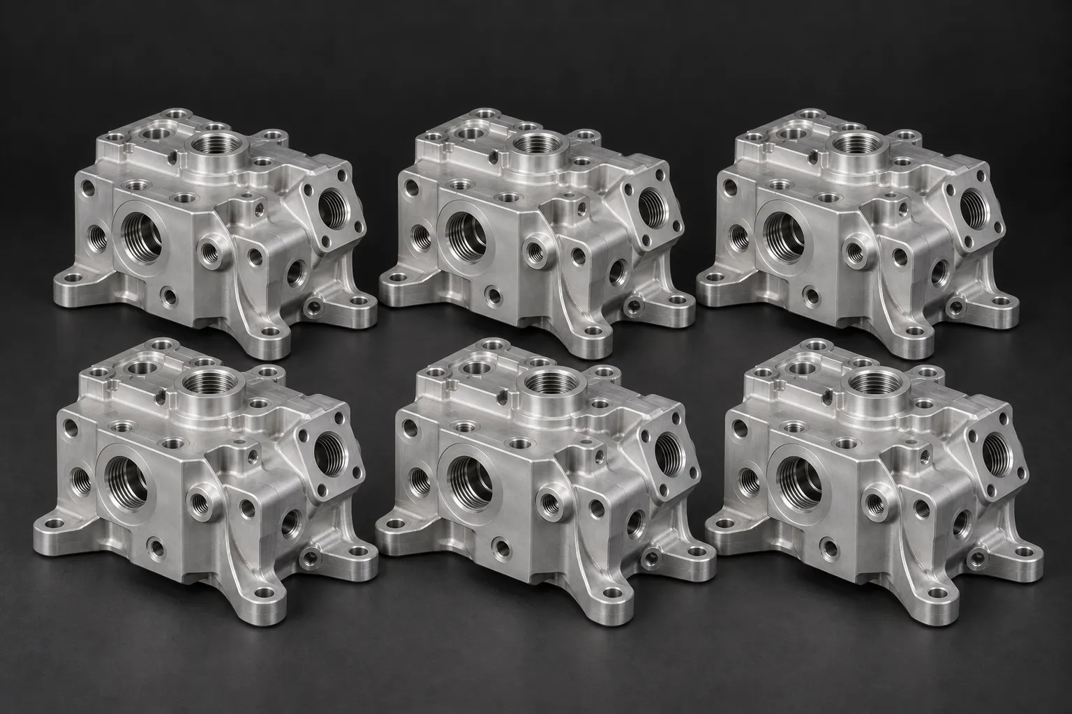
Over 100,000 parts delivered, on time or early every time, an average of 1.5 days ahead. Complex parts delivered when we said.

Miguel came up through Cosworth, Perkins and Caterpillar before founding MV in 2020. The standard those names set is the standard we machine to.
Cutting five faces in one setup removes the handling that introduces error. The relationship between features is held because the part is never unclamped and reclamped.
We machine impellers, manifolds and housings for oil and gas and food machinery, where a single part carries features on several faces and the fit between them matters.
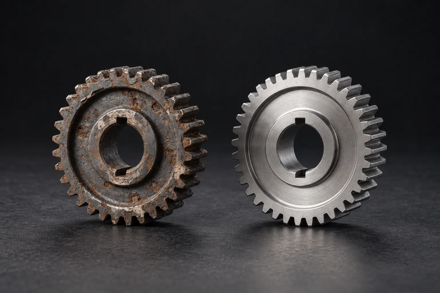
A worn or obsolete multi-face part with no drawing is a starting point, not a dead end. We recover the model and machine a part better than the original.
The 5 axis process from the part or model in your hand to the finished component on your bench. Four steps, one shop, an engineer on your job from the first call to delivery.
A CAD file in STEP, IGES or Parasolid, a 2D drawing, or the physical component. No drawing is fine. We measure the part and reverse engineer the model to machine from.

A real engineer reviews the geometry, the number of faces and setups, the material and the volume, then prices it within 24 hours. Straight advice, and an honest steer if a 3 axis mill would do the job cheaper.
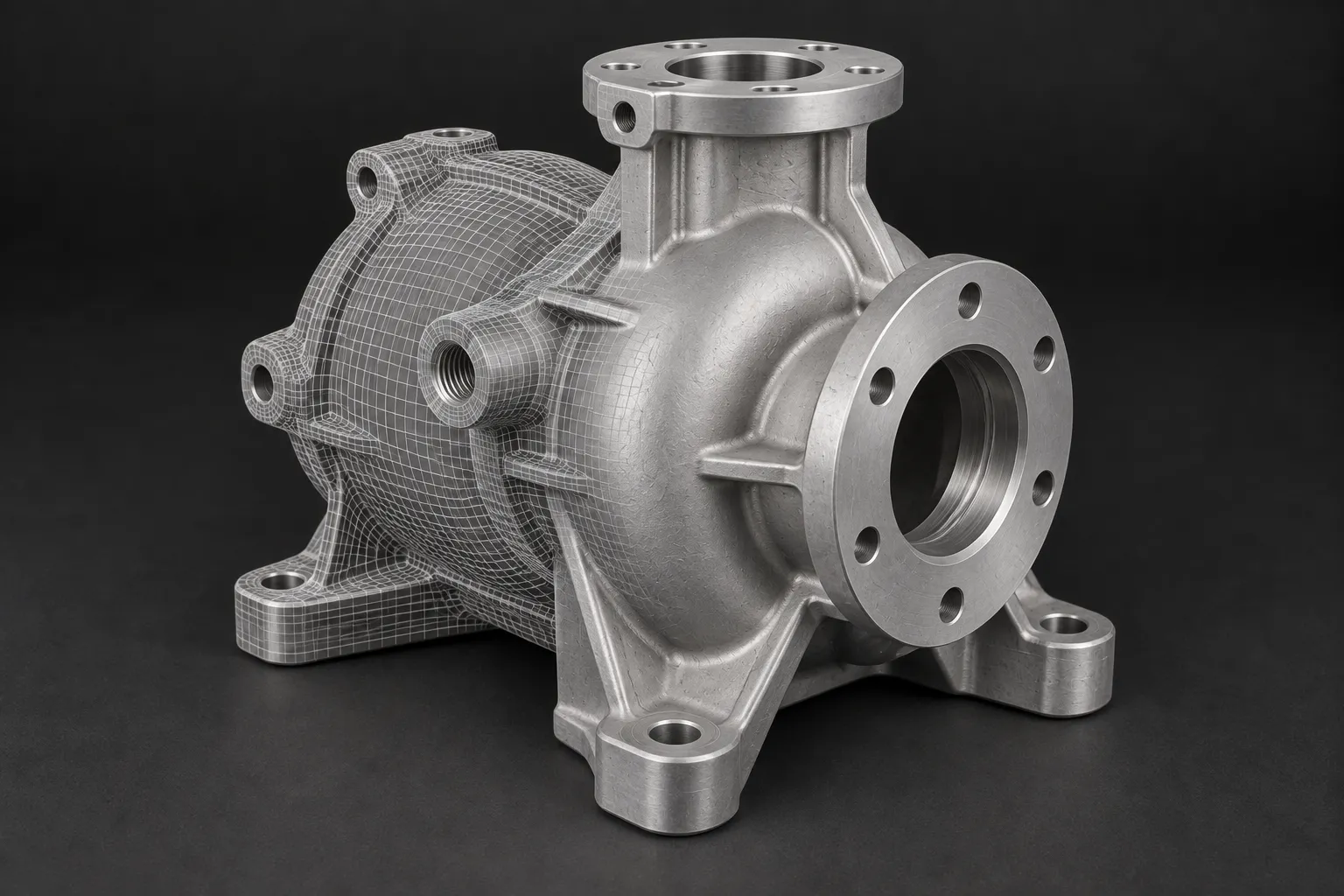
We programme the setups to minimise handling and protect the critical features, machine five faces in one fixturing, then prove the first article against the model before the run continues.
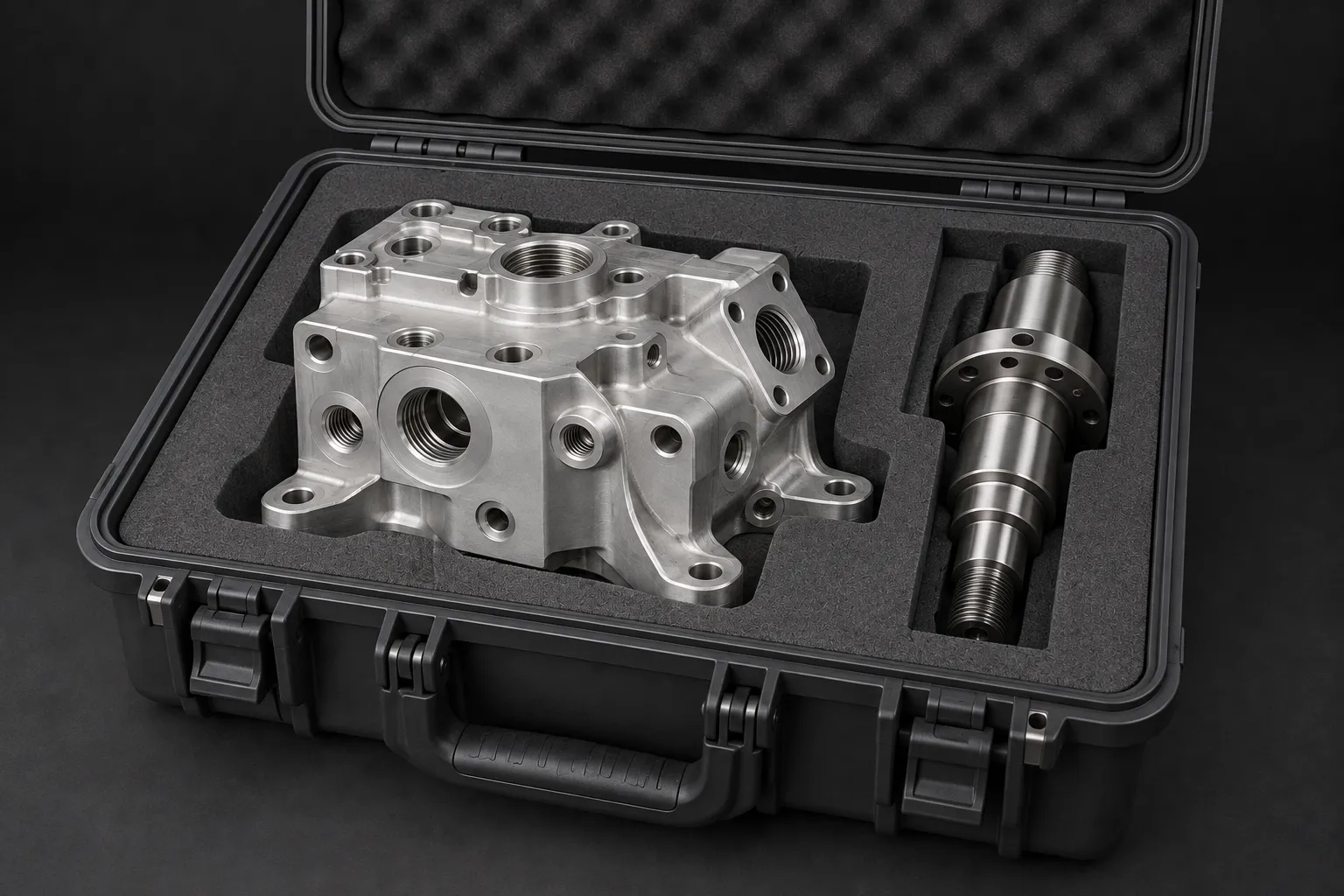
The finished component delivered on time or early, an average of 1.5 days ahead, ready to fit the assembly it was made for, with the model held on file for any reorder.
5 axis FAQs

Yes. This is our lead capability and the reason engineers bring their hardest jobs to us. We measure the worn or obsolete part by metrology or 3D scanning, rebuild it as a full CAD model, and machine the replacement on five axes. Because a 5 axis machine reaches features across several faces in one setup, we can reproduce a complex multi-face part accurately even when no drawing survives, holding the datums true from face to face. Where the original design caused the wear, we correct it as we rebuild the model, so the part comes back better than the original. Send us the sample and our engineers will recover the design and quote your 5 axis CNC machining within 24 hours.
5 axis machining reaches five faces of a component in a single setup, where 3 axis works one face at a time and needs the part re-fixtured to reach the rest. Moving the part or the tool head on two rotary axes as well as the three linear ones lets the cutter get to angled features, contoured surfaces, deep pockets and undercuts that a 3 axis pass cannot reach cleanly. The bigger gain is accuracy: every time a part is unclamped and reclamped a small error can creep in, so finishing a complex part in one setup holds the relationship between its features far more reliably. That is why tight-tolerance parts with several critical faces suit multi-axis machining. If you are unsure whether your part needs 5 axis or would be cheaper on a 3 axis mill, ask us and we will tell you straight.
We machine aluminium, steel, stainless steel and engineering plastics on five axes, among others, and the right choice depends on the duty the part has to do. Material behaviour matters as much in 5 axis as the geometry does: harder alloys and stainless need slower, more controlled cutting to hold a tight tolerance and a clean finish across contoured faces, while aluminium lets you run faster on complex forms like impellers and manifolds. For that reason we confirm the grade with you before we quote, so the toolpaths and the finish are planned around the actual material rather than a guess. If your part needs a grade outside the common families, tell us the specification and we will confirm whether we can hold it before you commit.
An engineer prices your 5 axis job within 24 hours, and it is a real engineer who reviews it, not an automated estimate. Our engineers review the geometry, the number of faces and setups, the material and the volume, because those drive the cost of complex CNC machined parts far more than the overall size does. We take on both single parts and production runs: a one-off is often a reverse engineering job, an obsolete impeller or housing with no drawing that we measure, model and machine as a single replacement, while a larger run is set once and every part comes off the same, checked against the first article. Send a CAD file, a drawing or a worn sample and you will have a costed answer inside a day.
Yes. We prove the first part against the CAD model before the rest of the run continues, so you are not paying for a batch that has drifted away from the drawing. On complex 5 axis parts this matters more than on simple ones, because a single setup carries many features and the first article confirms that the datums, the angled faces and the fits have all come out where the model says they should. If anything needs adjusting, we catch it on the machine rather than on delivery. Inspection against the model also means that when you reorder, the new batch matches the first, because we hold the model and the inspection reference on file. That gives OEM engineers a consistent, documented source for a repeat part.
For 5 axis work we typically hold around 0.05mm, and tighter on the critical features on request, confirmed against the part at quote stage rather than promised blind. We work from 3D CAD in STEP, IGES or Parasolid, which carry the solid geometry we need to programme the toolpaths, and we can work from a 2D drawing or the physical part where no model exists. We cannot machine from an STL, which is a surface mesh rather than a true solid, though it is fine as a visual reference. If you only have a worn sample, that is enough: we reverse engineer the model first, then machine from it. Tell us the tolerance the part has to hold and we will confirm we can meet it before you commit.
Angled holes, compound surfaces and features on several faces can make five-axis machining useful. The decision also depends on tool access, workholding and the relationships between critical features. Our engineers compare the practical manufacturing routes before recommending the approach.
Workholding is planned around the component’s geometry, rigidity and accessible surfaces. The part needs secure support without obstructing the cutting tool or distorting thin sections. Any temporary holding features or additional set-ups are considered when planning the manufacturing sequence.
Thin walls and deep features require careful review because tool deflection, vibration and material movement can affect the result. We assess the geometry and may recommend changes to radii, wall thickness or access. Achievable tolerances are confirmed for the actual component at quote stage.
Specify finish requirements where they affect sealing, sliding, appearance or later treatment. A uniform cosmetic requirement across every face can add unnecessary work. We distinguish functional surfaces from general machined areas and confirm any subsequent finishing process with the manufacturing plan.