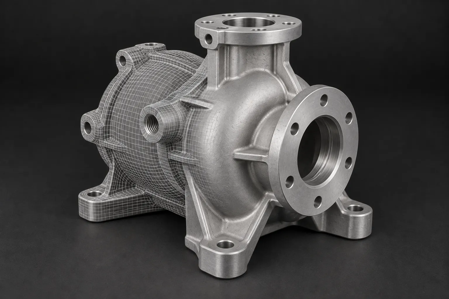
Start with the component you have. Our team assesses its geometry, condition and purpose, then recommends how 3D scanning can support a useful digital model. From a discontinued housing to a complex curved part, scanning gives our reverse engineering work a starting point. We agree the deliverables and critical features before the job begins.
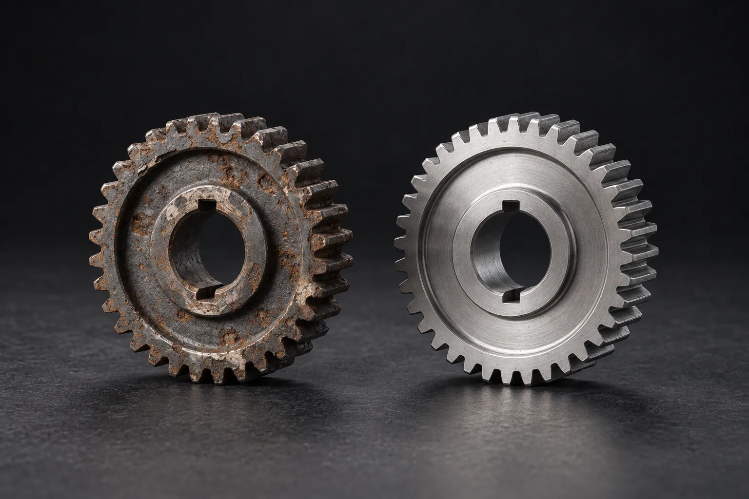
Start with a worn, failed or discontinued part. We reconstruct the design and agree improvements before manufacture.
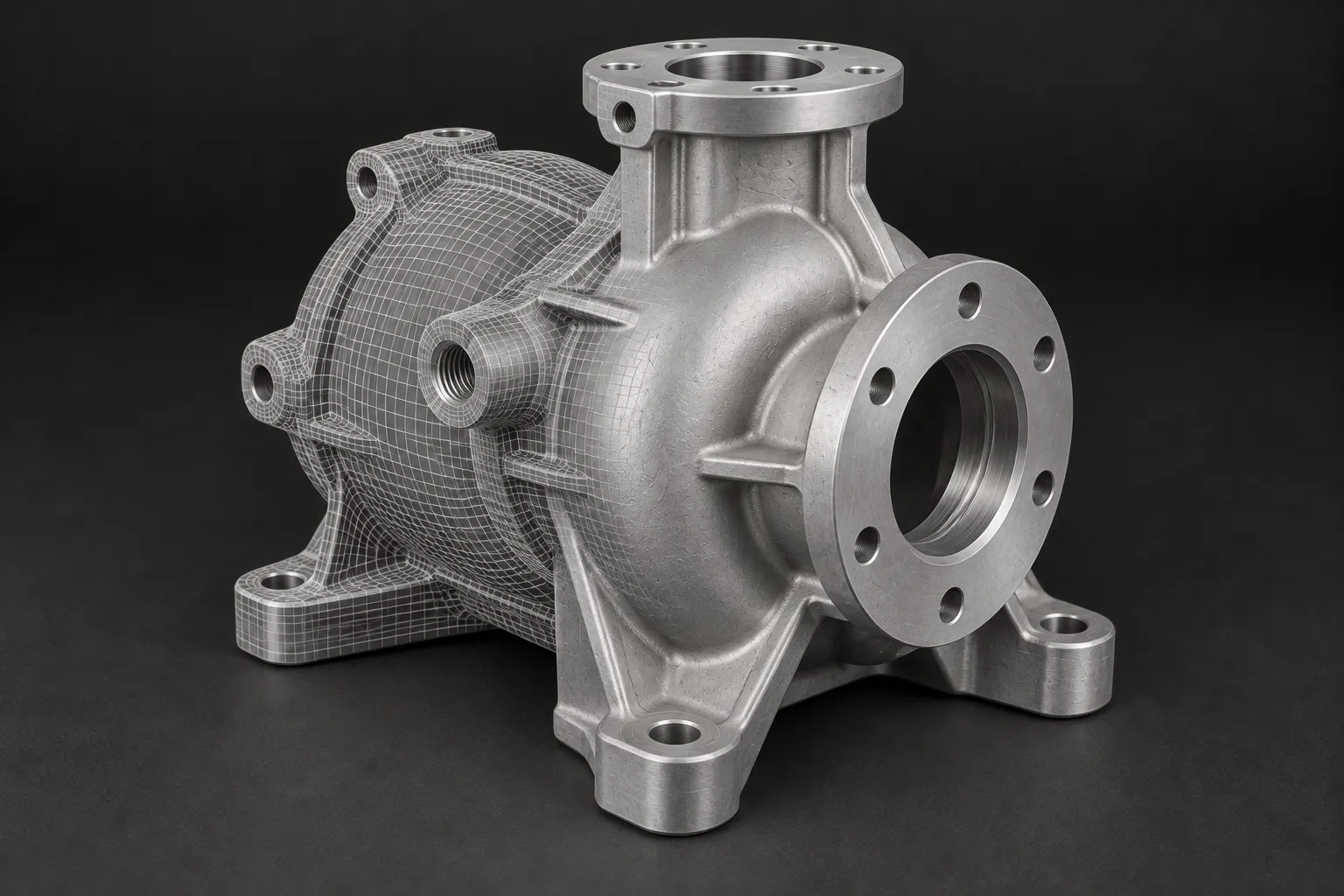
Digital surface capture to support CAD reconstruction and the wider reverse engineering job.
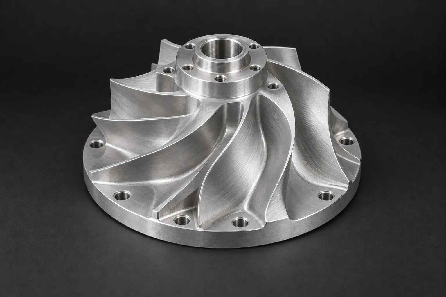
Machine angled features and complex surfaces, with the set-up planned around the critical relationships.
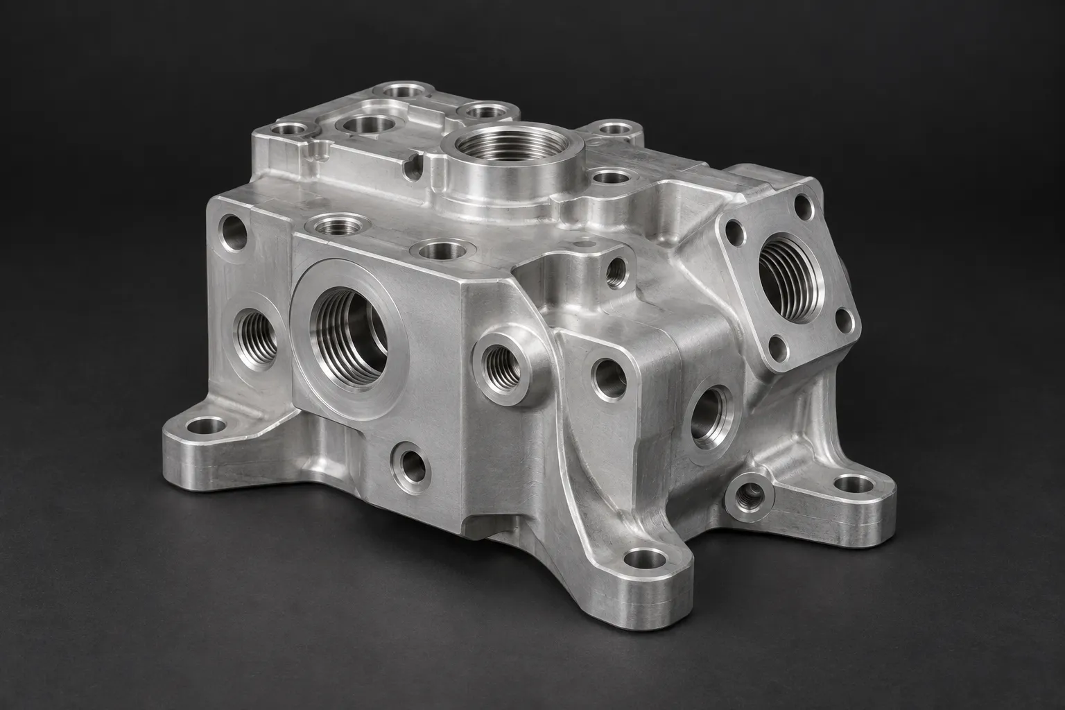
Milled housings, brackets and precision components in metals and engineering plastics.
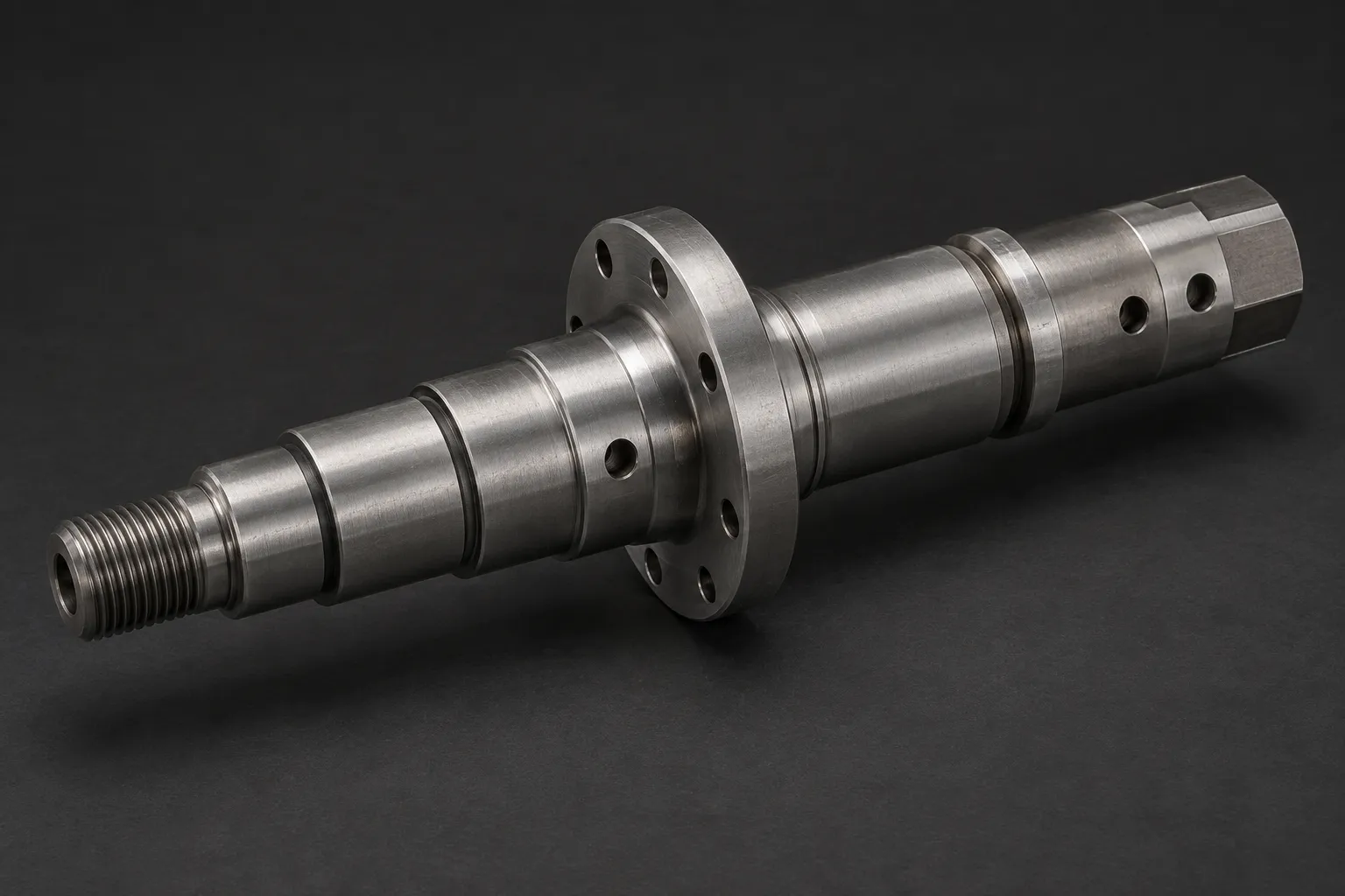
Stepped shafts, threaded fittings and housings, made to drawing or reverse engineered from a sample.
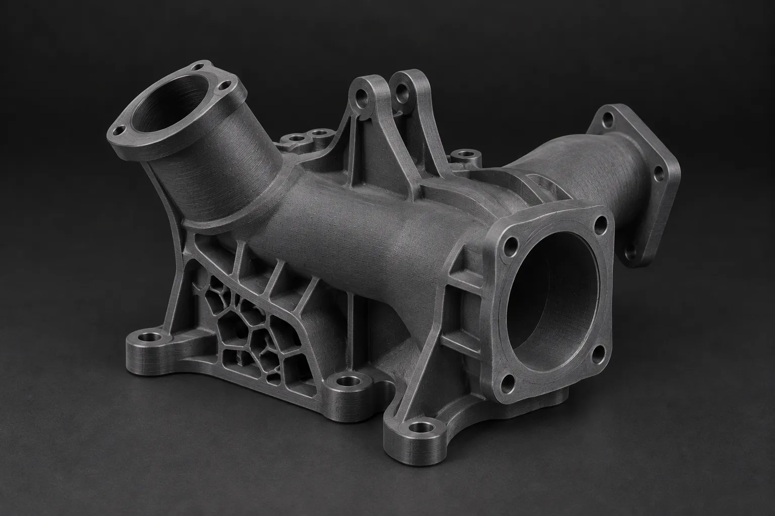
Bring us the application. Our engineers recommend the material and approach for your prototype or part.
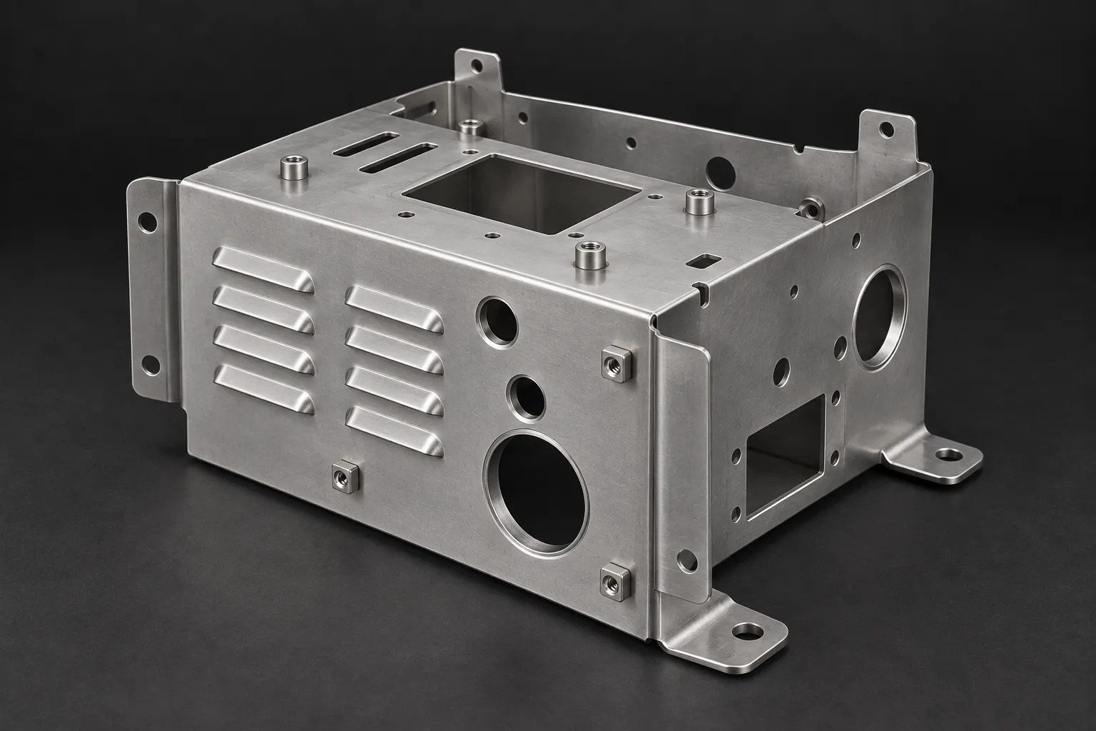
Brackets, panels and enclosures, developed around the bends, interfaces and finished assembly.
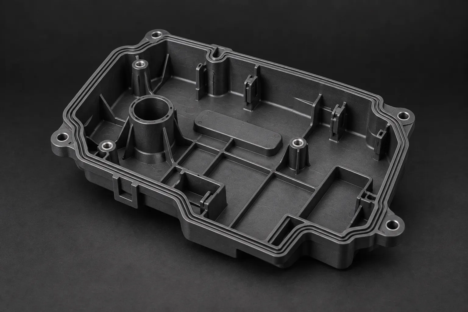
Moulded plastic components, with material, tool design and production requirements considered together.
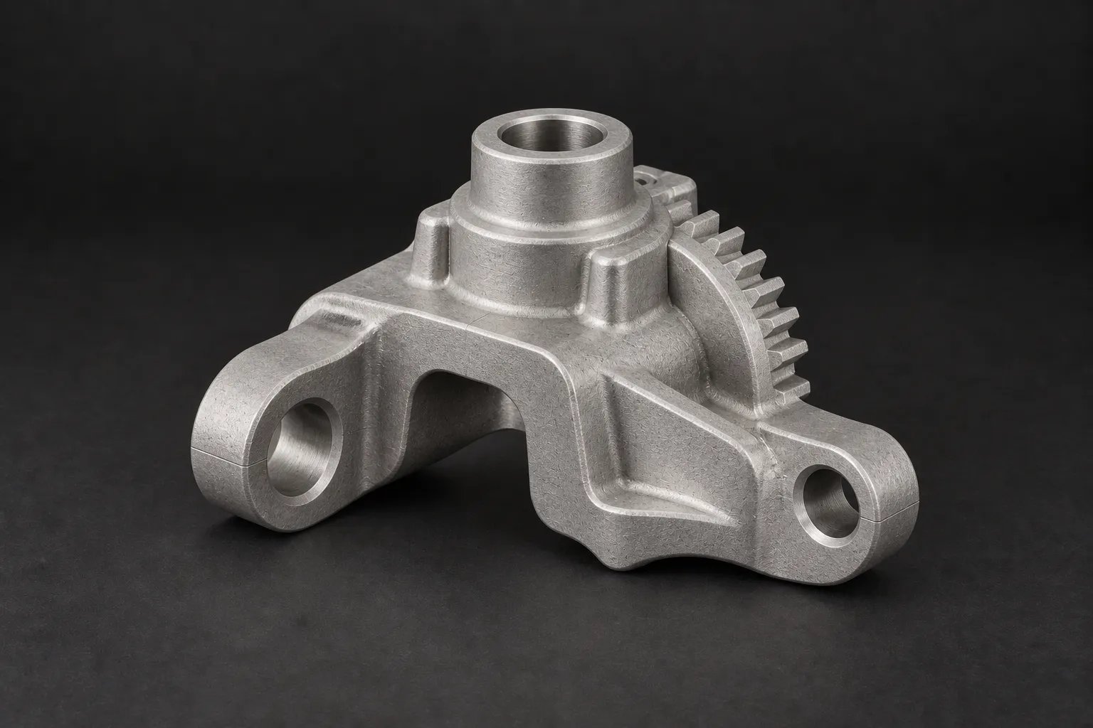
Small, complex metal components where geometry and quantity suit moulding and sintering.
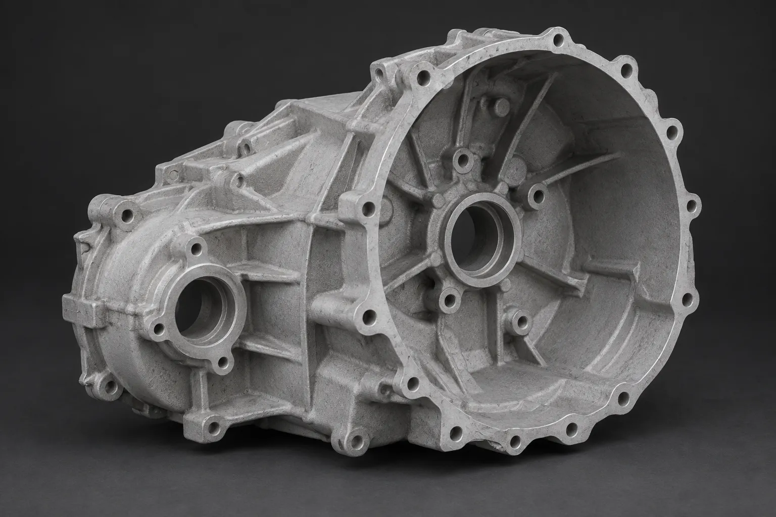
Aluminium housings and components, with casting geometry and any secondary machining planned together.
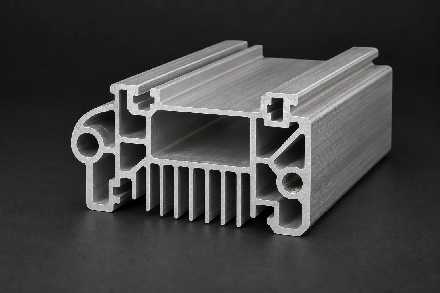
Custom sections developed for the application, then cut, machined and finished as required.
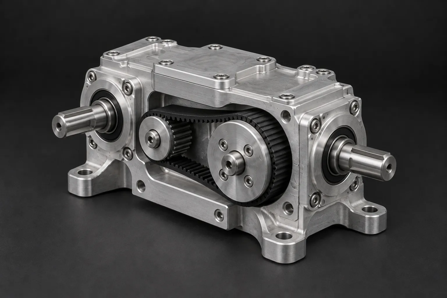
Manufactured and bought-in components brought together, with the interfaces and checks agreed first.
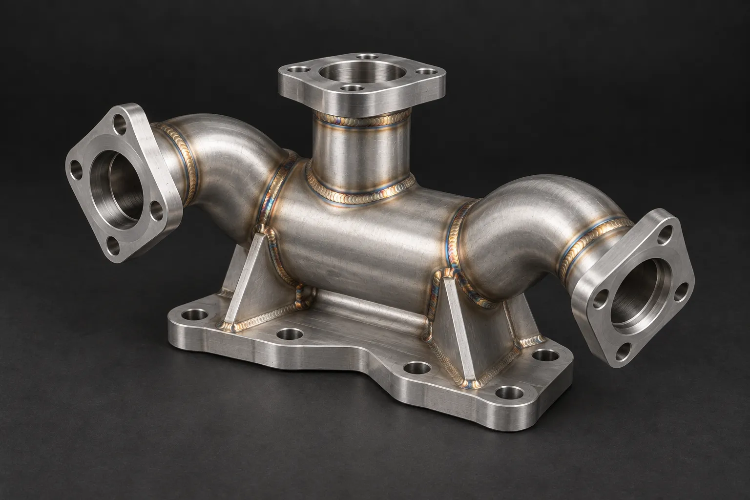
Welded components and fabrications, planned around material, joint access and distortion control.
3D scanning captures the accessible surfaces of a physical object as digital geometry. The resulting mesh describes the part as it is, including wear or damage. It does not, by itself, explain the intended dimensions, the material or why the part failed. MV puts that data in context. Our engineers review the component's function, identify the features that matter and agree whether you need a surface reference, a reconstructed CAD model or a route to manufacture.
Build a digital reference for complex external geometry that is difficult to describe from a few dimensions.
Use the captured surfaces to support CAD reconstruction, with deliberate decisions about design intent and worn features.
Agree which mating faces, bores and other features need additional dimensional checks.
Connect the digital work to reverse engineering, a printed prototype or manufacture of the replacement.
A failed component carries evidence of its working life. Copying every worn surface would copy the problem. Our team uses the captured geometry alongside the application, mating parts and any surviving information to separate the original design from damage. That work belongs within our reverse engineering service, where the aim is a replacement that is better than the original.
Send the component and whatever documentation survives. Photographs and a description help us decide what is needed before the part arrives.
We identify the mounting points, interfaces and clearance requirements that must remain consistent when the design is reconstructed.
Tell us what you want to achieve with the data. A visual record, a replacement part and a fit check can call for different deliverables. We will recommend a suitable scope after reviewing the component.
You do not need to choose the scanning method. The following information helps our engineers plan the work and identify any gaps.
Approximate overall size
Material, if known
Surface condition
Damage or missing areas
What the part needs to do
How it connects to other parts
Digital model or replacement
Required date and quantity
We agree the output before scanning begins. A surface mesh, an editable CAD model and a manufacturing drawing serve different purposes. Reconstruction and dimensional verification are separate engineering tasks, so the agreed scope makes clear what is included and which assumptions require your approval.
A digital description of the captured external geometry for review and further engineering work.
Geometry rebuilt around the intended form and critical interfaces, where CAD reconstruction is included in the scope.
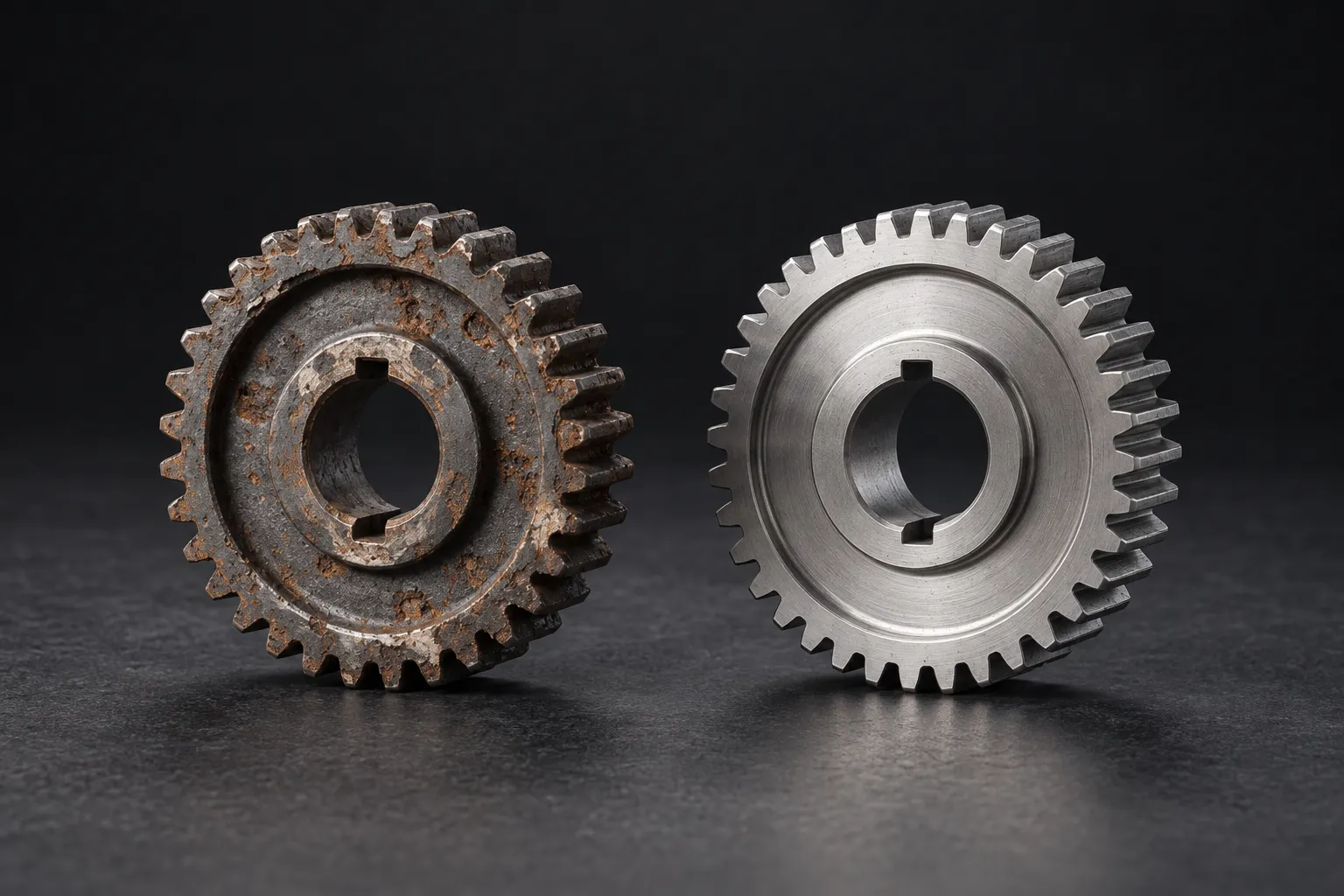
A clear record of worn areas, missing information and proposed changes for discussion before manufacture.
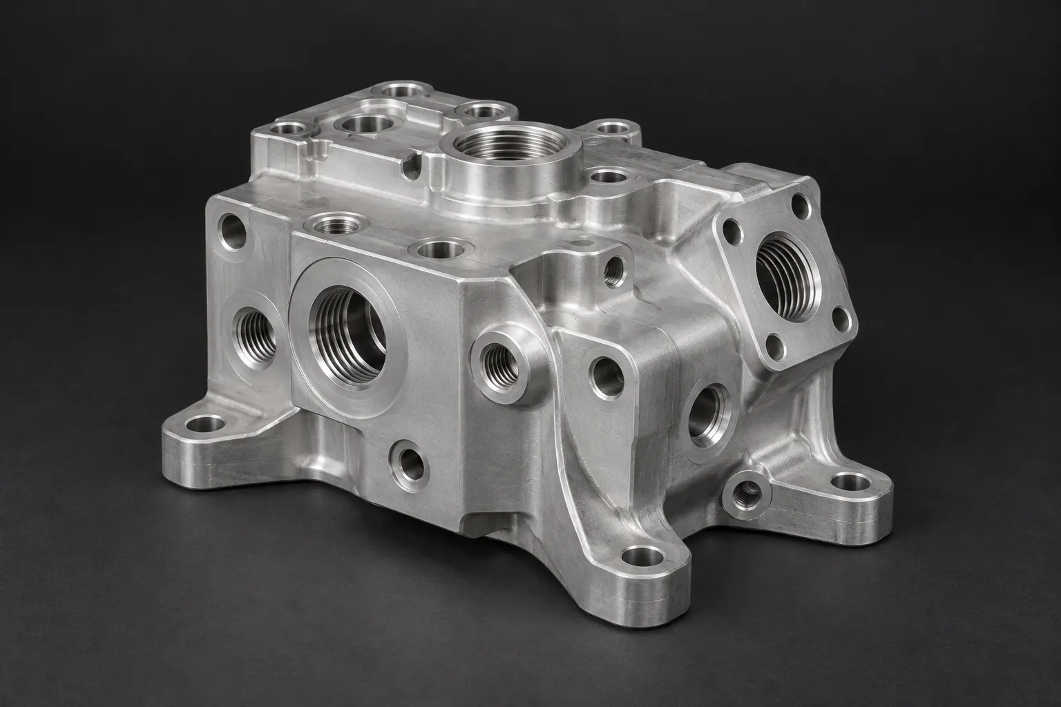
A recommendation for prototyping or production after the geometry, material and working requirements have been assessed.
The value is in what happens after the shape is captured. Our engineers connect the digital model to the part's job, its interfaces and the way it can be manufactured. You have a team that can explain the options and the limitations, and keep reverse engineering at the centre of the project.

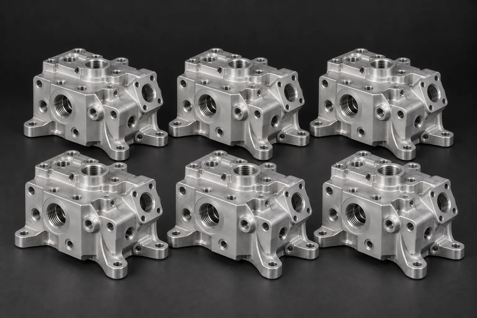
We start with the outcome you need. That keeps data capture, reconstruction and manufacturing decisions aligned throughout the project.

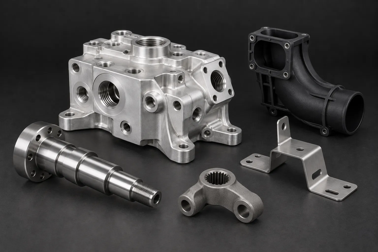
Miguel's background at Cosworth, Perkins and Caterpillar helped shape MV's approach. Our engineering team carries that focus on function, careful judgement and clear communication through the work.
Once the design is agreed, we can discuss 3D printing to assess fit or a suitable machining, casting or fabrication route for the finished component.
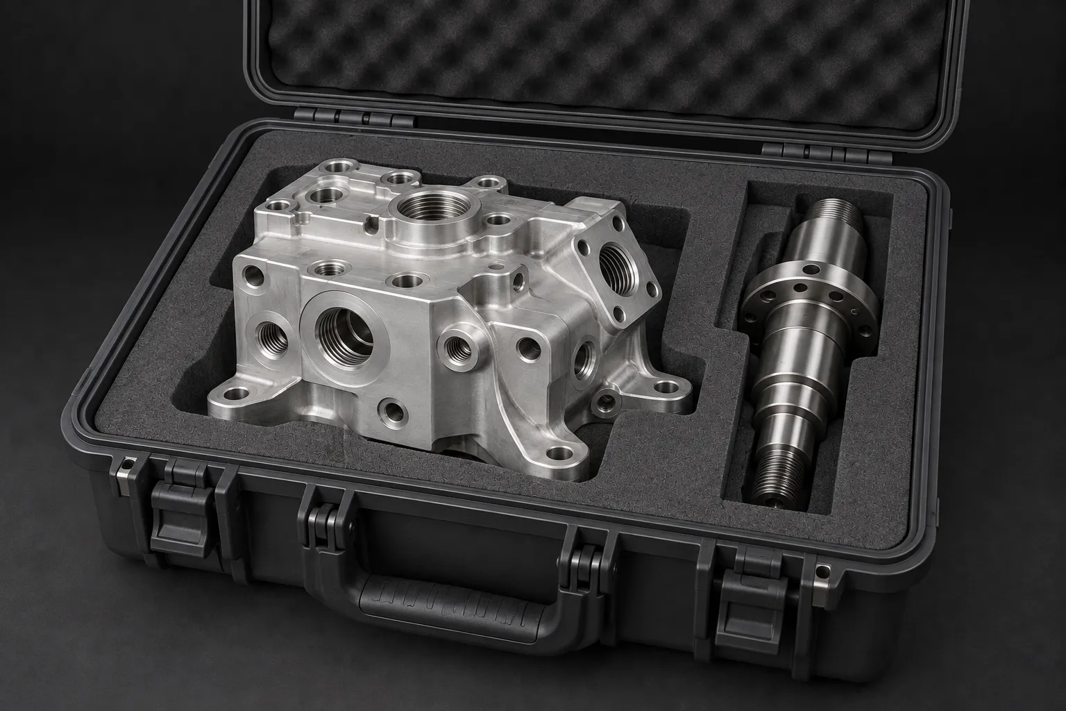
A housing that needs to seal, a bracket that must clear moving parts and a component that locates a bearing all need different checks. We plan around those requirements.
Scanning supports the wider reverse engineering job. We assess the original's weaknesses and agree practical improvements rather than reproducing wear in a new part.
Our team manages the scope, capture and engineering review, then helps you decide how the model should be used. The deliverables are agreed before work starts.
Send photographs, approximate dimensions and a description of what you need. Highlight damage, hard-to-access areas and any surfaces that must fit another component.

We review the component, the required output and the features that matter. You receive a clear scope covering data capture, any CAD reconstruction and the checks needed before the model is used for manufacture.
The accessible geometry is captured and reviewed. Where reconstruction is included, the model is developed around the agreed design intent, with worn or uncertain features raised for review.
We review the agreed output with you and explain what it is suitable for. If a replacement is required, the project continues through reverse engineering into prototyping or production.
3D scanning FAQs

No. A scan records captured surface geometry, usually as a mesh. A manufacturing-ready model needs engineering decisions about intended shape, fits and the features that were worn or damaged. We agree whether the job includes CAD reconstruction and any supporting drawings. Before manufacture, the important interfaces and acceptance requirements also need to be defined. Our reverse engineering service brings those tasks together.
We can assess it as a starting point. A scan records the condition of the part that is present, so it cannot recover a missing feature without other evidence. Mating components, an unworn sample, photographs and surviving drawings can help the team reconstruct the intended geometry. We identify uncertainties and agree how to resolve them before committing to a replacement design.
Send photographs, the approximate size, material if known and a description of the result you need. Tell us whether you need a surface record, a CAD model, a prototype or a finished replacement. Include any critical fits, damaged areas and required date. Our engineers review those details and confirm the scope, suitability and next steps.
The required accuracy has to be agreed for the particular component and its critical features. Shape, access, surface condition and the chosen method affect the result. A single headline number would not describe every feature reliably. We identify what must be checked and how the resulting data will be used before starting the job.
An optical scan needs a view of the surface. Deep bores, enclosed passages and concealed features may need a different approach or additional checks. Reflective, dark or transparent surfaces can also affect capture. We review the component first and explain preparation or access requirements. We do not assume an external scan describes the entire internal design.
Yes, the scanning work can support a wider reverse engineering project. We assess the part's purpose, reconstruct the design where needed and recommend the material and manufacturing route. A 3D printed prototype may help review form or fit before machining, casting or fabrication. The production method is selected for the application, geometry and quantity, with the important requirements agreed before manufacture.
Reflective, transparent or very dark surfaces can make optical capture more difficult. Surface condition and access are reviewed before selecting the scanning approach. If preparation is needed, we explain it first and consider whether it is suitable for the material, finish and intended use of the component.
Start with clear photographs, approximate overall dimensions and a description of the part’s function. Explain whether you need a surface reference, a reconstructed CAD model or a manufactured replacement. Highlight mating features and areas of wear so our engineers can plan the capture and checking work.
No. A simple shaft or bracket may be defined more efficiently by conventional measurement. Complex freeform surfaces can benefit from scanning, while critical fits may still need separate checks. We choose the method that produces a useful manufacturing definition for your reverse engineering project.
Scan data provides a record of the captured surface. Design changes are developed during CAD reconstruction and engineering review, rather than simply editing away visible damage. We agree which features must remain compatible and which can change before the replacement is manufactured.